ERM vibration motor characteristics that drive reliable haptics
Engineer-ready guide to ERM haptic strength, latency, drivers, mounting, qualification, and sourcing for stable production haptics.
Introduction
For an electronics OEM team, “ERM vibration motor characteristics” isn’t just datasheet trivia. These characteristics determine whether your haptics feel consistent across battery states, whether short pulses feel mushy, and whether your line build starts failing because a small tolerance shift moves current draw or start behavior.
At a practical level, ERM behavior is dominated by three truths:
Strength and frequency are coupled. With an eccentric rotating mass (ERM), the applied voltage sets motor speed, which sets vibration frequency—and the generated centrifugal force grows with speed. You don’t get to tune amplitude and frequency independently the way you can with resonant actuators.
Latency is inertia. You’re spinning a mass up and down. That gives you predictable ramp-up and tail behavior, but also limits “crisp” effects unless your driver actively helps.
The device matters more than the motor. Mount stiffness, enclosure modes, and contact points decide how much of the motor’s vibration becomes perceived haptics versus audible buzz or wasted energy.
This article maps key datasheet metrics and curves to design targets and driver settings, then closes the loop with what to validate from EVT through mass production—so your haptics are reliable, repeatable, and qualification-ready. If you’re building a sourcing-ready spec, you’ll end up translating ERM vibration frequency vs voltage and ERM vibration amplitude vs voltage curves into acceptance windows that your driver and mechanics can actually hold.
ERM characteristics and transients
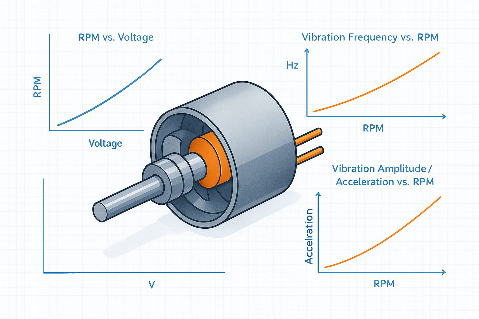
Amplitude & frequency coupling
ERM motors are DC motors with an off-center mass. The “vibration” you feel is the net centrifugal force from that unbalance. Two implications drop out immediately:
Vibration frequency tracks speed. If motor speed is RPM, the vibration frequency in Hz is simply RPM/60. This is a useful conversion when you’re trying to reconcile “it feels buzzier” with what the motor is actually doing at a given voltage (and load). See Makeability Lab’s vibromotor notes (RPM/60 and (F=m r \omega^2)).
Vibration force scales with speed squared. The centrifugal force magnitude is commonly expressed as:
(F = m \cdot r \cdot \omega^2)
Where m is eccentric mass, r is eccentricity radius, and (\omega) is angular speed. This is why a small speed shift (caused by supply droop, higher friction, or a stiffer mount) can change perceived strength more than you’d expect from “just a few hundred RPM.” Precision Microdrives uses the same relationship to explain why amplitude rises nonlinearly with speed in its AB-004 application note.
What to do with this in a product spec
If you have a target “feel,” avoid specifying only a motor voltage. Instead specify a device-level target like acceleration at the touch point (or a proxy measured at a repeatable reference location on the housing) at min/nom/max battery.
Expect a “good” ERM haptic design to be defined by an envelope, not a single point: a minimum start/feel threshold and a maximum noise/power ceiling.
Rise/stop and driver influence
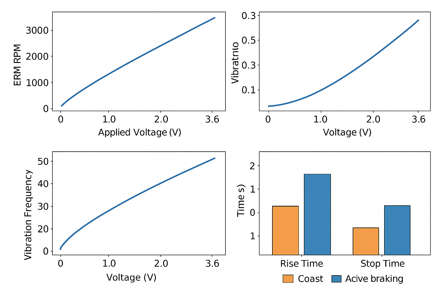
ERM response time is dominated by inertia: the motor needs time to accelerate the rotating mass to speed, and time to dissipate energy on stop. PowerElectronicTips “Haptics components, part 1: LRA, ERM, and piezo actuators” (2021) summarizes this clearly: ERMs have defined spin-up and spin-down behavior because of the eccentric mass, and it typically takes on the order of tens of milliseconds to reach near-target output.
Precision Microdrives goes one step further in Precision Microdrives “AB-029: Voltage Vs Frequency Vs Amplitude” by splitting the transient into measurable pieces:
(When you’re writing requirements, it’s often useful to explicitly call these out as ERM motor rise time and ERM motor stop time targets, because they directly affect how “crisp” short UI effects feel.)
Lag time: time to reach a small threshold vibration (example: 0.08 G)
Rise time: time to reach a fraction of steady-state amplitude (example: 50%)
Stop time: time to decay after drive removal
The driver matters because it can change both the initial torque and the stop dynamics:
Overdrive (start boost): briefly drive above the steady-state level to reduce lag/rise time, then settle to the desired amplitude. This is a controlled way to fight inertia, but it must be bounded (thermal and life impact).
Active braking: reverse the voltage (or otherwise apply an opposing torque) to stop faster. Power Electronic Tips notes that reversing drive voltage acts as braking; Precision Microdrives discusses braking explicitly in AB-029.
Key Takeaway: With ERM, “snappy” haptics are rarely a motor-only decision. They’re a driver + waveform + mechanical coupling decision.
Frequency content & perception
Engineers often focus on motor acceleration in free air, but perception is filtered by the human body and your device mechanics.
A few practical implications worth carrying into your tuning plan:
Frequency shifts change “texture.” Because frequency tracks speed, any supply or load effect that changes RPM will change the perceived sharpness/buzziness.
Mounting and enclosure modes can dominate. If your housing has a resonance near your operating band, the device can amplify a narrow frequency component, converting “haptic” energy into audible noise.
Measure at the touch point when you can. A motor spec that looks great on a vendor’s test fixture can feel weak in a heavy device or when decoupled by foam.
When your goal is reliable production haptics, treat frequency content as a system topic: motor + mount + enclosure + user contact.
Electrical and control design
Open-loop PWM/DC practices
Open-loop drive (DC or PWM) is still the most common way to bring up ERM quickly in EVT.
Key considerations (especially relevant when your key spec is ERM vibration frequency vs voltage and ERM vibration amplitude vs voltage):
Start voltage margin: ERMs usually have a specified start voltage (the minimum needed to reliably start). Precision Microdrives notes that operating below start voltage risks intermittent non-start.
Supply droop and peak current: Startup current can be materially higher than steady-state. Budget for the worst-case battery state and worst-case line impedance.
PWM frequency selection: Choose PWM high enough to avoid audible artifacts from the electrical drive itself, but be mindful of switching losses and EMI.
Practical control advice that tends to survive EVT→MP:
Use a transistor or driver stage sized for startup current.
Add flyback protection (diode or integrated clamp) and local decoupling near the driver.
Define a minimum on-time / kick to overcome stiction at cold temperatures and low battery.
Closed-loop drivers (Smart Loop)
If you’re qualifying for consistent feel across temperature, battery, and unit-to-unit variation, open-loop PWM often becomes the limiting factor.
A closed-loop ERM driver (or a “smart loop” approach) typically estimates or measures motor speed using back-EMF and adjusts drive to hit a target speed (and therefore a target vibration frequency and approximate amplitude).
Closed-loop can help with:
Battery variation: holding a more consistent speed as VBAT sags
Lot-to-lot variation: compensating for small differences in resistance/friction
Temperature variation: maintaining behavior at cold start
It won’t fix poor mechanics, but it can shrink the electrical part of your variability budget.
EMI and supply variation
ERM drivers can become an EMI and supply-noise problem because they combine:
inductive switching
pulsed load current
long harnesses/lead wires in some products
Mitigations that are usually worth the PCB area:
Local bulk + high-frequency decoupling near the driver
Controlled edge rates (where available)
Good return-path layout (don’t let motor current share sensitive analog ground paths)
If the motor is off-board, consider harness routing and shielding strategy early—not after EMC fails.
Mechanical integration
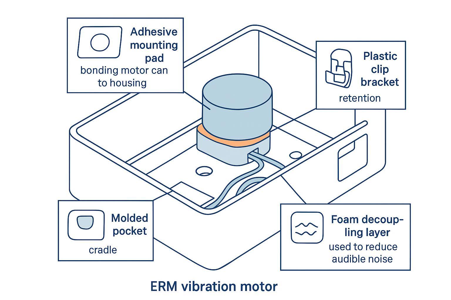
Mounting & coupling methods
Mounting is where ERM designs most often win or lose in production.
A stiff, repeatable mount tends to:
increase transfer to the touch point (stronger perceived haptics at the same electrical drive)
reduce unit-to-unit variability
reduce “mystery buzz” that comes from rattling interfaces
But mounts also have trade-offs:
very stiff coupling can excite enclosure modes and create audible noise
very soft decoupling can make haptics feel weak and slow
Mass loading & decoupling
Mass loading is a blunt but effective tool: a heavier local mass can reduce the amount the motor “moves itself” and increase the amount of energy that couples into the enclosure in a predictable way.
Decoupling (foam, elastomer) is useful when:
you need to reduce audible buzz transmitted through thin walls
you need to prevent exciting a panel resonance
But decoupling increases variability unless it’s tightly controlled (material batch, compression, assembly tolerance).
A decision-stage recommendation: if you decouple, define the decoupler as a qualified component with incoming inspection (thickness, hardness, compression set), not an afterthought piece of foam.
Connectors & strain relief
If your ERM is cabled or uses lead wires:
Add strain relief so flex doesn’t transfer into the solder joint or motor tabs.
Avoid sharp bends at the motor exit; they become fatigue points under vibration.
Define connector retention and contact resistance limits; intermittent contact can look like “random haptic failure” in the field.
Reliability and qualification
Life & cycling profiles
ERM lifetime is strongly influenced by how you drive it:
total on-time (duty cycle)
number of start/stop cycles
peak drive (overdrive)
braking strategy (reverse drive adds stress if overused)
Qualification planning tips:
Define a cycling profile that matches your UX (notification buzzes vs short clicks).
Capture end-of-life criteria that are measurable: “fails to start at X V,” “current increases by Y%,” “acceleration drops below Z at reference point.”
Environmental & mechanical tests
At decision stage, the goal is repeatable evidence that the haptic design survives your real world:
temperature (including cold start)
humidity exposure (especially for wearables)
mechanical shock/drop
vibration exposure (shipping + use)
The important part isn’t the acronym—it’s that your test setup keeps mounting, preload, and measurement location consistent so you can separate “motor drift” from “fixture drift.”
Variability & inspection
Unit-to-unit variation comes from motor tolerances and your assembly.
Incoming/line checks that often pay for themselves:
Start/functional check at the minimum guaranteed start voltage for your design
Current draw at a controlled voltage (as a proxy for friction/load changes)
A quick vibration proxy check (accelerometer fixture or microphone-based buzz proxy) on a sample basis
Precision Microdrives highlights that current increases with torque load as vibration energy is extracted; that relationship is why current is a useful screening metric when something changes mechanically.
Compliance and sourcing
Documentation & QMS
At decision stage, documentation is part of risk control.
A practical “ready-to-qualify” package typically includes:
datasheet with voltage/RPM/amplitude curves
tolerance definitions (where applicable)
material declarations as required by your program
reliability data relevant to your duty cycle
change control expectations
When you’re working with INEED Electronics, align documentation delivery early—especially if you need consistent connector part numbers, wire specs, and revision-controlled drawings. INEED Electronics’ vibration motor hub and ERM category pages outline customization options (connectors, lead wires, electrical parameters) and provide an ERM e-catalogue PDF as a starting reference:
EVT/DVT lead time & MOQ
Common pitfalls in haptics sourcing are not technical—they’re logistical:
EVT needs fast iteration; DVT needs configuration lock; MP needs capacity and change control.
Connector/harness customization can dominate lead time if it’s not standardized.
Plan for:
a fast EVT sampling loop (multiple builds)
a DVT freeze point where motor + mount + drive waveform become controlled items
an MP incoming inspection and traceability approach that matches your product risk
Customization & second source
Customization is often required for real products (lead length, connector, housing geometry, encapsulation). The decision-stage question is: how do you customize without creating an unmanageable single-source risk?
A practical approach:
Customize in layers: keep the motor core as standard as possible; customize interfaces (connector/wire/housing) with clear drawings and revision control.
Define “equivalence criteria” that a second source must meet (start voltage margin, current envelope, speed/feel window at min/nom/max VBAT, and mechanical envelope).
If your program needs durability against sweat, dust, or cleaning exposure, consider whether an encapsulated vibration motor variant should be qualified in parallel to reduce late surprises:
ERM vs LRA in practice
Selection heuristics
Use ERM when:
you need a strong “rumble” notification
cost and simplicity matter
your UX can tolerate ramp-up and tail
Bias to LRA when:
you need crisp short “tap/click” effects
you need tighter consistency across battery states
you can invest in driver tuning and resonance management
Driver implications
ERM can be driven with relatively simple DC/PWM stages, but production-grade feel often benefits from:
start boost (overdrive)
active braking
(optionally) closed-loop speed regulation
LRA almost always needs a driver that can handle resonant drive and (ideally) closed-loop resonance tracking.
Tuning patterns & UX
For ERM, common tuning patterns are:
Ramp-in + hold + brake-out for alerts (reduces perceived mush and tail)
Short pulses only when your driver can brake effectively; otherwise the motor spends most of the pulse ramping
For a decision-stage build, lock:
waveform library (named effects)
minimum VBAT behavior
acceptance criteria at touch point
Conclusion
Reliable haptics with ERM motors come from treating “ERM vibration motor characteristics” as a system problem:
Coupled amplitude/frequency means your supply and load variation directly becomes feel variation.
Inertia-driven rise/stop means your driver technique (overdrive + braking) is a first-class design variable.
Mechanical coupling determines whether energy becomes haptics—or audible buzz and variance.
Qualification readiness requires test fixtures, acceptance criteria, and documentation discipline—not just a motor part number.
Next steps: prototype with a controlled mount, measure acceleration and transient behavior at your touch point across min/nom/max battery, then qualify the final motor + driver + mount as a single subsystem.
If you want a design-in review, start with one build-ready data pack: target haptic effects (timing + perceived strength), enclosure constraints, VBAT range, and connector/wire requirements. From there, INEED Electronics can help you shortlist ERM options (including INEED coin vibration motors) and define the documentation and inspection set you’ll need for DVT and ramp.
FAQ
What is the difference between ERM vibration frequency vs voltage and amplitude vs voltage?
ERM vibration frequency vs voltage reflects how motor speed changes with applied voltage (frequency ≈ RPM/60). ERM vibration amplitude vs voltage tracks how vibration strength changes—and it rises nonlinearly because centrifugal force scales roughly with speed squared. In practice, load, mounting stiffness, and supply droop shift both curves, so validate them in-device at min/nom/max VBAT.
What is a typical ERM motor start voltage and how should I spec it?
Start voltage is the minimum voltage where the motor reliably begins spinning from rest. Because stiction, temperature, and assembly variation affect starting, you should spec start performance as a pass/fail requirement at the minimum battery condition (and worst-case temperature), not only at room temperature on a vendor fixture. Many teams also add a short “kick” (overdrive) window in the waveform to improve start reliability.
How can I reduce ERM motor rise time and stop time for crisper haptics?
To reduce ERM motor rise time, use a bounded overdrive at the start (higher voltage/PWM duty for a short time) to increase starting torque. To reduce ERM motor stop time, use active braking (reverse or dynamic braking, depending on your driver). The best settings are device-specific: too much overdrive/braking can raise peak current, EMI, heat, and mechanical stress, so confirm limits during EVT/DVT.
What should I measure to qualify ERM haptics in production?
For repeatable, qualification-ready ERM behavior, measure a small set of metrics at a consistent fixture location (ideally near the touch point):
Vibration acceleration (or a validated proxy) at min/nom/max VBAT
Start reliability at the minimum guaranteed start condition
Current draw envelope at a controlled drive level (screen for friction/load changes)
Transient behavior (lag/rise/stop) for your key effects
These checks help you catch both motor variation and mechanical coupling issues before they become “random buzz” field failures.
When should I choose an LRA instead of an ERM for haptics?
Choose an LRA when you need tighter “click/tap” effects, better consistency across battery states, or more control over how the haptic feels in short pulses. LRAs can be tuned around resonance and often deliver a cleaner, more repeatable sensation in compact devices—especially when you pair them with the right driver and mechanical stack. If you’re evaluating that path, start with INEED’s linear resonant actuator options and define your target effects (timing + perceived strength) before locking the mechanical mount.