Haptic Feedback Motor Integration Best Practices for Engineers
How to select, integrate, and validate ERM, LRA, and piezo haptic motors for wearables, medical, and consumer devices from EVT to DVT, covering resonance, EMI, and reliability.
Introduction
A haptic feel rarely fails because the motor was weak. It fails because the motor, driver, mechanics, and firmware were never treated as one system. When you chase a consistent click or a clean buzz on a smartwatch, a medical alert, or a game controller, the parts that decide success sit outside the actuator datasheet: resonance behavior, mounting, EMI, and how a unit behaves once it is built into your real stack at volume.
This guide maps the path from early prototype (EVT) through design validation (DVT) for haptic feedback motors. We cover the actuator types you will actually weigh, a selection framework that starts from your constraints rather than a part number, and the integration practices that separate smooth ramps from field returns. Along the way we flag the reliability, EMI/EMC, and compliance expectations that buyers and QA teams should lock down before volume. The perspective is practical, from engineers and sales staff who build linear resonant actuators (LRAs) every day and want you to skip the painful rework loops.
Actuator landscape
ERM vs LRA overview
The eccentric rotating mass (ERM) motor spins an off-center weight, so it is easy to drive and cheap. Start and stop are slow, the feel is a rumble rather than a crisp tap, and output drifts with battery voltage because drive is roughly DC. If your goal is a basic alert, an ERM vibration motor is a fair and low-cost pick.
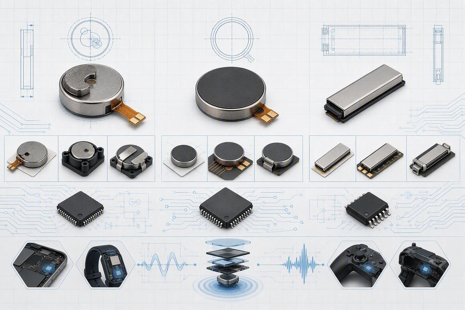
The linear resonant actuator (LRA) shakes a spring-mounted mass along one axis instead of spinning a weight. Round LRAs like INEED's vibrate along the Z axis, perpendicular to the motor face. The tradeoff is drive: an LRA needs an AC signal near its resonant frequency F0 to work well, so it costs more and needs a driver IC. Sizes run from a compact 6 x 2.5 mm coin up to larger units, with F0 typically in roughly the 65 to 260 Hz range depending on the model, and rated drive in Vrms AC. In return you get fast rise and a fall that stops in a fraction of the ERM time, stable frequency that does not sag as voltage drops, and efficient output near resonance. That is why LRAs show up in phones, wearables, automotive HMI, and higher-end controllers.
Piezoelectric options
Piezo actuators bend or expand a crystal under high voltage. They cover a much wider frequency range, roughly from DC up to a few hundred hertz, so they can shape sharper and more varied effects than a resonant actuator that is stuck near one F0. The catch is drive electronics. Piezo needs a higher-voltage boost stage and careful handling in layout and safety, which pushes up bill-of-materials cost and design effort. Reach for piezo when you need broad-frequency texture and high resolution and the extra drive budget is acceptable.
Voice-coil use cases
Voice-coil and magnetically levitated ("maglev") actuators drive a coil against a magnetic assembly for linear stroke with very low force ripple and low-noise feel. They suit larger or premium surfaces where you want a strong, clean, sustained force with fine control, such as high-end trackpads, automotive touch panels, or VR/AR controllers. They take up more space and power than a coin LRA, so treat them as a use-case decision rather than a default. When an LRA suits the app, compact round actuators like the INEED LRA linear resonant actuators cover the common wearable and handheld sizes at much smaller footprints.
Selection framework
Constraints and tradeoffs
Start from the space and power you can afford, not from a wish-list of effects. Write down the diameter and thickness budget, the operating voltage and current you can really supply, and the mounting footprint. Then decide which quality you cannot give up. Fast, crisp timing pushes you toward LRA or voice-coil; lowest part cost and simplest drive push you toward ERM; broad frequency and high resolution push you toward piezo.
Tolerance stack-up matters as much as the headline spec. On an LRA, Vrms, F0, and the force figure (listed as Grms or Gp-p) only mean something when you fix the mounting condition, the foam or adhesive thickness, the waveform, and the measurement jig. Compare parts the same way every time or the numbers will mislead you.
Driver and control needs
An LRA is only as good as its drive. Recommended driver approaches include parts like the TI DRV2604/DRV2605 or cost-effective Awinic AW86223/AW86927, which many teams pick to fit their PCB plan. Keep auto-resonance tracking on in normal use. A driver that senses back-EMF and locks to resonance matters because F0 shifts with mounting, temperature, aging, and the exact stack you build, and off-resonance drive quietly cuts output, especially under load.
Budget the supply for worst case, not nominal. Account for battery droop, line impedance, startup current, and any overdrive you need to break stiction at cold or low-battery conditions. If the rail clips or the driver cannot start the actuator, your "good on the bench" effect dies in the field.
Application-driven picks
Let the product decide the actuator. A smartwatch alert wants low mass, low power, and tight coupling to the wearer, where a compact LRA earns its keep. When the same small footprint has to deliver a crisper, higher-resolution feel, a linear magnetic haptic actuator such as INEED's MAG1020BEL40 becomes the model to compare. A medical device wants repeatable, traceable output and predictable behavior across lots, which favors a well-characterized LRA or, where regulated, a documented part with reliability data. A consumer gadget chasing perceived sharpness wants fast response and no parasitic buzz, again pointing to resonance-tracked LRA drive. If you only need an unmistakable notification at the lowest cost, stay with ERM.
Integration best practices
Electrical and firmware
Treat the driver and actuator as a single electrical block. Place the haptic driver close to the actuator connection, keep the high-current traces short and wide, and put local decoupling right at the driver supply. Add clean enable and gain control so firmware can shape attack and release instead of stepping a raw square wave.
In firmware, define each effect as a target acceleration and duration at a repeatable reference point, then tune once and freeze it. If the driver can report tracked resonance, back-EMF, undervoltage, or overcurrent flags, log them during EVT and DVT. Those numbers explain why two units feel different on the line and give you a fast root-cause when a haptic feedback motor complaint shows up later.
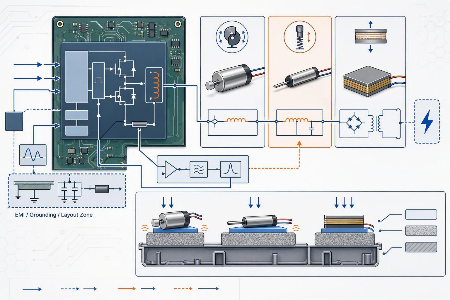
The image above sums up the integration stack: a resonant LRA is driven through a sensing driver IC that closes a resonance-tracking loop, a piezo option adds a high-voltage stage, and all of it sits on a PCB whose layout and grounding decide how much switching noise leaks into radios, sensors, or audio.
A short look at how an LRA moves can help: this manufacturer demo shows the working path of an LRA vibration motor, driven by an AC signal along a single axis near resonance.
Mechanical coupling
The part the user feels is not the actuator alone, it is the couple between actuator and enclosure. Mount stiffness, adhesive thickness, bracket rigidity, and foam cushioning all change amplitude and frequency response. Too hard a mount can break accelerations into buzz; too soft a mount drains the energy before it reaches the user.
Avoid hard stops, loose retainers, and unintended secondary resonances near displays, cameras, or microphones. Keep clearances consistent. On wiring and connectors, add strain relief and avoid sharp bends at the motor exit, because an intermittent connection reads as a random haptic failure long after you have shipped. On sensitive apps, pick a mounting scheme early and freeze it before you tune effects, so the feel you validate matches what you produce.
Power, EMI, thermal
Brace the power path for current spikes and treat the actuator trace as EMI-sensitive. Keep switching currents contained, mind your return paths and grounding, and shield or distance the actuator from radio and audio blocks where you can. Then check temperature rise at the actuator, driver, and nearby plastics under long pulses and repeated events at the worst ambient, not just the cozy nominal case.
Checklist for the integration phase, at a glance:
Keep resonance tracking enabled and log tracked F0/BEMF.
Budget supply for startup, overdrive, and battery droop.
Local decoupling close to the driver; compact, short high-current routes.
Control grounding and return paths to protect radio, sensors, and audio.
Freeze mounting stiffness and foam/adhesive before tuning effects.
Strain relief and consistent clearances on wiring.
Validate thermal rise under worst-case pulse load.
When you need a working actuator quickly, INEED supports fast samples and customization of wire, connectors, FPC, and mounting for EVT/DVT validation.
Validation and readiness
EVT functional checks
At EVT, measure the real assembly, not the bench part. Confirm acceleration at the touch point or a repeatable proxy across min, nominal, and max battery. Verify startup reliability, the current envelope, and effect timing. Sweep the resonance behavior and check whether the chosen driver holds F0 as the stack and temperature change. This is the stage to catch a feel that only works on the bench.
DVT reliability tests
At DVT, prove the production-like build. Run unit-to-unit variation, corner temperature behavior, and any life testing your program demands, such as repeated actuation cycles. Depending on the product, that includes temperature exposure, humidity, free fall or drop, and shipping vibration. Confirm the final PCB and mechanical build still hit the haptic target with real production tolerances attached, not hand-picked samples.
Compliance and sourcing
Lock compliance expectations before ramp. For most markets that means things like RoHS and REACH; regulated medical and some industrial builds add documented QMS and reliability evidence. If your sourcing process uses approved vendor lists, confirm the supplier can show certification, provide the compliance documents you need, and back the part with incoming-inspection data rather than promises. Confirm lead time, MOQ, and how flexible the vendor is for engineering builds versus volume, because a great motor that arrives too late or only in giant lots still stalls your ramp.
Conclusion
Treating haptics as a system is what separates a shipped, repeatable feature from a source of field returns. Pick the actuator from your real constraints, not a favorite part. Keep LRA resonance tracking on, budget the driver for worst case, control mechanical coupling and EMI, and validate from the first prototype through production-like builds at DVT. The do's are plain: freeze your stack early, log driver telemetry, compare specs under identical mounting. The don'ts are just as clear: skip worst-case power, ignore return paths, tune against a bare bench part, or wait until volume to think about compliance and supply.
Metrics worth tracking through the program are resonance stability, unit-to-unit force spread, rise and fall time, thermal rise, and EMI emissions next to your radios and sensors. Readiness means those numbers hold on production-built units with real tolerances, the compliance paperwork is in hand, and the supplier can match your lead time and MOQ.
Questions worth asking before you buy
Here are three questions procurement staff and engineers should answer before committing to a haptic motor, and that you can raise with the INEED sales engineers or any supplier you are evaluating.
1. How will you measure "feel" so it survives the handoff from EVT to DVT? If you only specify a motor voltage, the tune will drift as the stack changes. Decide that you will measure acceleration at a repeatable touch point, agree on the mounting and foam setup, and confirm the driver can hold resonance across temperatures. A supplier who asks for your size, target force, and mounting method up front is usually the one who will not surprise you later.
2. Do you have reliability and compliance data for this part, or only a datasheet? Ask for life-test evidence under your duty cycle, temperature and humidity exposure, drop and vibration results, and the RoHS/REACH or QMS documents your market needs. Confirm the data comes from a production-consistent build and covers unit-to-unit spread, not one golden sample.
3. Can the vendor support samples and engineering changes before volume? Verify lead time and MOQ for prototype quantities, and whether they can customize wire length, connectors, FPC, and mounting so the motor fits your real enclosure. A motor that needs connector rework at ramp adds cost and schedule risk, so settle the assembly fit while you can still change it.