
Linear Resonant Actuator (LRA) Design and Integration Guide
Engineer-focused guide to LRA specs, driver ICs, resonance tracking, mechanical/electrical integration, and EVT/DVT validation.
Introduction
This guide is written for electronics OEM product teams—EE, ME, QA, and sourcing—who need predictable haptics in a space-, power-, and schedule-constrained program. Choose a Linear Resonant Actuator (LRA) when you need crisp “click-like” feedback, faster response than ERM motors, and stable feel across battery voltage and temperature—as long as you’re willing to design around resonance.
You’ll learn:
LRA fundamentals (what resonance means in practice)
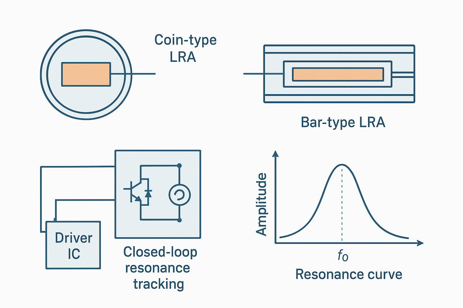
how to read key specs and select an actuator (coin vs bar)
what modern driver ICs actually do (tracking, BEMF sensing, overdrive/brake)
integration details that usually surface late (mounting, EMI/ESD, headroom)
validation and characterization methods you can run in EVT/DVT and use for ramp controls
how to think about documentation, compliance, and supplier readiness
How to use this across builds:
EVT: prove the actuator + driver can hit target acceleration/latency in your mechanical stack.
DVT: lock down mounting, tolerance stack-up, and robustness (drift, noise, EMI, ESD).
Ramp: manage lot variation, incoming inspection criteria, and supplier change control.
LRA fundamentals
Operating principle and resonance behavior
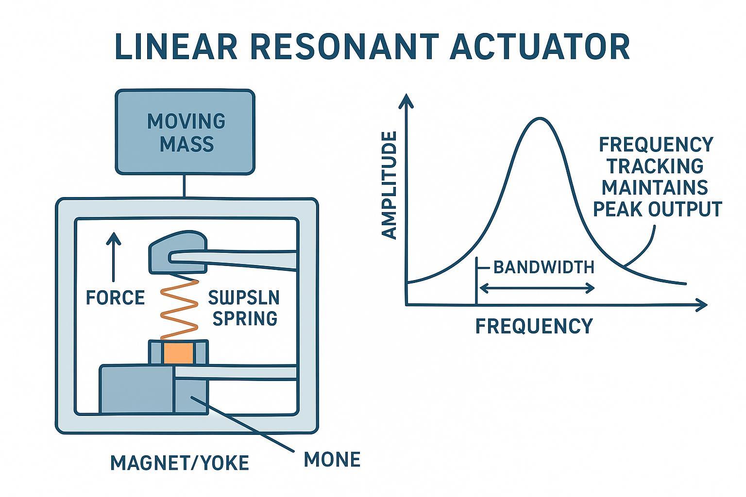
An LRA is easiest to think of as a spring–mass system driven by an electromagnetic actuator (often described as a voice coil). When you drive it near its resonant frequency (f0), mechanical amplification does the work: you get higher acceleration per unit power.
Linear oscillation vs rotating mass
If you’re searching “what is LRA motor” or “lra motor explained,” the simplest mental model is motion type:
A linear resonant actuator (LRA motor) moves a small mass back and forth in a straight line (linear oscillation) on a spring. It’s tuned to a resonant frequency, so it’s strongest and most efficient when driven near f0.
An ERM motor spins an eccentric rotating mass. Vibration comes from rotational imbalance, so it feels more like a ramping “buzz,” and it’s less dependent on hitting one exact frequency.
This linear vs rotating difference is why an LRA vibration motor usually feels crisper—and why its performance depends more on resonance tracking and mechanical mounting.
The catch is bandwidth. LRAs typically have a narrow “sweet spot,” and small frequency errors can noticeably reduce output. Precision Microdrives notes an example where being about 5 Hz off resonance reduced vibration amplitude by ~40%, and also points out that resonance can shift with mounting method, orientation, environment, aging, and lot variation (Precision Microdrives, “When LRAs don’t behave as expected”).
That’s why LRA integration is less about “apply voltage and vibrate” and more about maintaining the right frequency under real conditions.
Drive requirements: AC excitation, H-bridge, amplitude envelope
Unlike a typical DC motor, an LRA needs AC excitation (a reversing drive) to oscillate the mass. In practice, you usually provide:
an H-bridge output stage (inside a driver IC) to alternate current through the coil
a drive waveform at or near f0 (often sine-like or shaped), plus an amplitude envelope to control perceived strength
Key implications for design:
Your system must provide enough voltage headroom for the driver to generate the required Vrms at the coil.
If you’re generating the waveform in firmware (vs. using a library inside the driver), you must manage both frequency and amplitude smoothly—sharp changes can create audible artifacts or “double taps.”
Response, efficiency, and limits vs ERM
LRAs are often chosen over ERM (eccentric rotating mass) motors because they can feel cleaner (less “spin-up mush”) and be more energy-efficient at the target sensation. Many LRA designs also show faster rise/stop behavior than ERM in comparable haptic use.
Attribute | LRA motor (linear resonant actuator) | ERM motor (eccentric rotating mass) |
|---|---|---|
Motion type | Linear oscillation of an internal mass | Rotating eccentric mass |
Feel | Crisp, “click-like,” more repeatable | Buzzier, more “ramp-up” |
Response | Typically faster start/stop with overdrive + braking | Slower spin-up/spin-down |
Voltage sensitivity | More stable when driven at resonance | Amplitude often varies more with voltage |
Control requirements | Usually benefits from closed-loop resonance tracking | Can run with simpler drive (often PWM) |
Mechanical sensitivity | High: mounting stiffness can shift f0/output | Moderate: mounting still matters, but less resonance-driven |
Typical use cases | Phones, wearables, haptics requiring sharp effects | Low-cost vibration alerts, simpler feedback |
The limits to accept up front:
You’re integrating a resonant device; performance can drop quickly off-frequency.
Driver choice matters more; a generic PWM output is rarely enough.
Mechanical coupling can make or break the end-user feel.
Specs and selection
Typical specifications for an LRA vibration motor
Datasheets vary by vendor and test method. Treat these as starting points and validate in your housing, because mounting and adhesives can shift resonance.
What you’ll typically see specified:
Resonant frequency (f0)
Acceleration / vibration strength (e.g., Grms, G peak-to-peak)
Rated voltage / drive level (and any allowed overdrive)
Current draw at a specified drive condition
Coil resistance / impedance
Dimensions and mass (diameter/length, Z-height)
Example “typical” specs (illustrative; values depend on model):
Example | Form factor | f0 | Acceleration | Drive level | Current | Size |
|---|---|---|---|---|---|---|
A | Coin LRA | ~170–260 Hz | ~1.0–2.0 Grms | ~1.8–2.5 Vrms | ~60–120 mA | ~6–12 mm Ø, ~2.5–4 mm thick |
B | Bar LRA | ~150–180 Hz | ~1.2–2.5 Grms | ~2.0–3.0 Vrms | ~80–180 mA | ~8–10 mm × ~3–4 mm × ~2–3 mm |
Practical rule: if your driver can report tracked resonance or BEMF metrics, log them during EVT/DVT—those numbers often correlate with “why this unit feels different” on the line.
Key parameters: f0, Q/bandwidth, impedance, voltage/current, acceleration
For selection, focus on the parameters that control whether you can hit your target haptic feel in your actual product stack:
Resonant frequency (f0): where the actuator produces maximum output. Because f0 can shift after mounting, treat datasheet f0 as a starting point, not a final truth.
Q / bandwidth: higher Q usually means narrower bandwidth (more sensitive to frequency error). Narrow bandwidth increases the value of closed-loop resonance tracking.
Impedance / coil resistance: drives current draw and the driver’s ability to achieve commanded acceleration without saturating.
Rated voltage/current: check both steady-state and any overdrive limits; you’re often constrained by battery rail and boost capability.
Acceleration output: may be specified as Grms or peak-to-peak. Use it as a comparative metric and plan to re-measure in your housing.
Key Takeaway: If you don’t control frequency (or your driver can’t track resonance), f0 and bandwidth will dominate user-perceived consistency more than “nominal acceleration” on a loose test fixture.
Size, axis orientation, acoustic noise, lifetime and reliability
Selection in real products is multi-dimensional:
Size and Z-height: haptics competes with batteries, antennas, and mechanical ribs. Small LRAs can be harder to mount consistently (adhesive area, stiffness).
Axis orientation: LRAs typically vibrate along a defined axis (often described as Z-axis in handset/wearable stacks). Make sure your mechanical stack couples that motion into what the user touches.
Acoustic noise: “buzz” and “tick” issues are often mechanical (rattles, hard stops, loose adhesive) but can be aggravated by waveform edges and clipping.
Lifetime / reliability: look for test method clarity, not just a headline number. For example, INEED’s LRA overview describes a common life test mode of 2 s on / 1 s off for 1 million cycles (~833 hours) for many models (INEED Electronics Linear Resonant Actuator overview). Treat this as a reference point and align it to your own mission profile.
Selection workflow and tradeoffs vs ERM
A practical selection workflow (especially for EVT) is:
A quick LRA motor selection checklist
Use this checklist when you shortlist parts or review RFQ responses:
Confirm your target effect: click, buzz, ramp, or texture—and translate it into acceleration and timing targets.
Choose a target frequency band (your “feel” baseline) and verify your chosen linear resonant actuator can hit it after mounting.
Decide on driver strategy: prefer closed-loop resonance tracking for higher-Q designs and for products with adhesive or stack-up variation.
Check voltage headroom at end-of-life battery: can the driver still deliver the required Vrms without clipping?
Review current draw vs your event budget (including overdrive), and verify thermal limits in worst-case ambient.
Lock down mechanical details that shift f0: adhesive type/thickness, bracket stiffness, and keep-outs.
Plan production controls: incoming checks (f0 window, resistance), and how you’ll handle lot drift.
This keeps your “lra motor explained” decision grounded in the two realities that matter most: resonance and mechanical coupling.
Define “good haptics” in measurable terms
target acceleration range at the touch surface
target rise time and stop time
power budget per event
noise limits (dBA at a defined distance)
Pick the actuator category
If you need crisp, repeatable “button feel,” an LRA is usually the right starting point.
If cost and simplicity dominate, ERM may still be acceptable—but verify latency and consistency.
Match f0 to your intended effect
Higher frequencies can feel “tighter,” but your stack-up and user coupling matter.
Select the driver approach
Closed-loop resonance tracking if you expect drift (you do), or if your Q is high.
For a concise internal comparison reference, see INEED’s explainer on ERM vs LRA differences.
Driver ICs and control
Closed-loop resonance tracking, BEMF sensing, overdrive and braking
Closed-loop LRA drivers exist for one reason: LRAs are sensitive to drive frequency, and resonance can drift.
Many modern haptic driver ICs track resonance by monitoring back-EMF (BEMF)—a voltage generated by the actuator’s motion that can be sensed and used to infer the optimal drive frequency. TI’s application note on Benefits of Auto-Resonance Tracking (SLOA188) describes how auto-tracking improves consistency and efficiency when resonance varies.
Two control features matter for user experience:
Overdrive: a short, higher-energy push to reduce startup latency (used carefully within actuator limits).
Braking: actively damping the actuator to stop cleanly, reducing “after-buzz” and improving perceived sharpness.
Mainstream drivers: TI DRV2624/2625 and Renesas DA728x interfaces
Mainstream parts for compact devices typically provide a complete output stage plus control interface:
TI DRV2624 / DRV2625: closed-loop LRA/ERM drivers with an auto-resonance engine that monitors BEMF; useful when you want the driver to manage frequency tracking and provide diagnostics. See the TI DRV2624 datasheet and TI DRV2625 datasheet.
Renesas DA728x: haptic drivers supporting resonant LRA drive modes and frequency tracking; a common reference is the Renesas DA7282 datasheet.
Design note: treat the driver choice as a system architecture decision. It affects your power rails, EMI behavior, test hooks, and even production calibration options.
Firmware control: I2C/PWM/RTP, waveform libraries, diagnostics
Most LRA driver IC workflows fall into three firmware patterns (and each needs its own haptic integration testing plan):
Library-based playback (sequencer / internal memory)
Pros: fast bring-up, consistent effects, less firmware waveform work.
Cons: less control unless you build a “haptics abstraction layer.”
Real-time playback (RTP)
Pros: dynamic effects (e.g., UI interactions), smooth amplitude control.
Cons: host timing matters; you need to validate latency and jitter.
PWM / external control modes
Pros: simple interfaces for some platforms.
Cons: it’s easy to lose the benefits of closed-loop tracking if you treat the LRA like a generic load.
Diagnostics to prioritize for EVT/DVT:
actuator presence / fault flags
overcurrent / undervoltage events
resonance tracking status and reported f0 (if available)
Embed video (one, public):
Integration and validation
Applications: where LRA motors are commonly used
An LRA motor is most valuable when you want consistent, “button-like” haptics with tight timing. Common application patterns:
Smartphones: crisp UI clicks, keyboard/tap feedback, camera shutter feel. Priorities: fast start/stop, low audible noise, consistent feel across battery.
Smart bands / smartwatches: notification patterns and subtle cues. Priorities: power efficiency, small Z-height, stable performance across temperature and skin coupling.
Game controllers: short, punchy effects that layer with audio. Priorities: wide effect palette, mechanical robustness, repeatability across units.
Medical and health devices: alarms and user guidance where reliability matters. Priorities: predictable output, documentation/traceability, and validation over the full environment range.
If you’re choosing between an LRA vibration motor and ERM for any of the above, decide early whether you can support resonance tracking and mechanical control—those two choices largely determine success.
Mechanical mounting and coupling: coin vs bar, isolation, adhesives
Mechanical integration is where LRA programs succeed or fail.
Coin vs bar (practical differences):
Coin LRAs are compact and easy to place, but can be sensitive to mounting stiffness and adhesive uniformity.
Bar LRAs can couple more effectively into a structure depending on constraints, but require careful alignment and mechanical support.
Mounting guidelines that hold up in EVT:
Control the mount stiffness and adhesive thickness; resonance and output amplitude can shift.
Avoid creating hard-stop rattles: keep clearance consistent and watch for loose brackets.
Use isolation where needed to prevent vibration energy from exciting microphones, IMUs, or display stacks.
⚠️ Warning: If you change adhesive, bracket material, or local rib geometry between EVT and DVT, treat it as a haptics design change that can shift resonance and acoustic noise—not a “ME-only” update.
Electrical design: supply headroom, layout/EMI/ESD, protection
Common electrical failure modes are predictable if you plan for them:
Supply headroom: confirm the driver can generate your required Vrms at the coil at end-of-life battery voltage and worst-case temperature.
Layout: keep H-bridge switching loops tight; separate noisy drive paths from sensitive analog and RF where practical.
EMI: validate with your actual waveform set, not just a single tone in the lab.
ESD: treat external interfaces and exposed metal as coupling paths; add protection appropriate to your product environment.
Characterization: acceleration vs voltage, latency/stop time, tracking robustness
A validation plan that prevents “late haptics surprises” should include:
Acceleration vs voltage at (a) nominal f0, and (b) ± a small frequency offset. This reveals how sensitive your stack is to drift.
Latency and stop time with and without overdrive/brake features enabled, using your real waveform library.
Tracking robustness: check performance across temperature corners and across multiple units (lot variation). Precision Microdrives highlights that resonance can shift with mounting and aging—validate that your control approach maintains consistent feel (see Precision Microdrives’ earlier note in this guide).
Practical test tip:
When comparing builds, measure both at the actuator (accelerometer fixture) and at the user touch point (housing). The “felt” acceleration can change even when the actuator output is identical.
Compliance and sourcing
Documentation, RoHS/REACH, and QMS alignment for wearables/medical
If your device ships into regulated or compliance-sensitive markets, treat documentation as part of the design, not paperwork:
Request RoHS/REACH declarations and material disclosures early.
Align the supplier’s quality system to your program risk. For medical or automotive-adjacent programs, consistency of change control and traceability often matters as much as the actuator’s nominal specs.
Prototyping to ramp: samples, MOQs, lead times, customization
Expect the sourcing profile to change across phases:
EVT: speed of samples and engineering responsiveness matter most.
DVT: stable specs, revision control, and repeatable test data matter most.
Ramp: lead time, MOQ, yield stability, and incoming inspection hooks dominate.
Partner note (≤30 words): INEED Electronics supports LRA selection, rapid samples, and integration guidance from EVT through ramp, including customization of electrical parameters and packaging for OEM builds.
Supplier evaluation: capability, test data, CAD, and support SLAs
A practical supplier evaluation checklist (useful for RFQs and vendor qualification):
Capability: model range, axis options, customization boundaries, and volume capacity.
Evidence: life test method, sample size, and environmental test coverage.
CAD + integration data: STEP/2D drawings, recommended keep-outs, and mounting guidance.
Lot control: tolerance controls on f0 and output, and how resonance drift is monitored.
Support SLAs: response time for EVT bring-up issues, root-cause turnaround, and PCN/change notification policy.
Conclusion
Selecting and integrating a Linear Resonant Actuator (LRA) is ultimately about controlling resonance in a real mechanical stack—not just picking a part with a good headline acceleration number. If you want a deeper internal explainer, see INEED’s article on how an LRA works.
Key takeaways:
Resonance (f0) and bandwidth (Q) determine how sensitive your haptics will be to mounting and drift.
Closed-loop resonance tracking using BEMF is the most reliable path to consistent feel across units and conditions.
Integration is interdisciplinary: ME mounting and EE power/layout decisions both move the needle.
EVT/DVT characterization (acceleration vs voltage, latency/stop time, tracking robustness) prevents late-stage surprises.
Next steps:
Shortlist 2–3 candidate LRAs and confirm f0/output in your EVT mechanical stack.
Choose a driver architecture (e.g., closed-loop tracking) and define firmware control mode (library vs RTP).
Build a DVT validation matrix covering temperature corners, unit-to-unit variation, and EMI/ESD with production-like layouts.
If you want a practical starting point for actuator options and typical specifications, review your shortlisted actuators’ datasheets and request sample guidance aligned to your program constraints.
FAQ
1) What is an LRA motor, in plain terms?
An LRA motor (a linear resonant actuator) is a haptic actuator that moves an internal mass back and forth on a spring. It produces its strongest, most efficient vibration when driven near its resonant frequency (f0), which is why many designs use resonance tracking.
2) Why can the same LRA vibration motor feel different after assembly?
Because mounting changes the system. Adhesive type/thickness, bracket stiffness, and the local mechanical stack can shift f0 and damping (Q), changing acceleration, latency, and even audible noise. That’s why it’s important to characterize the linear resonant actuator in your real housing during EVT/DVT—not only on a vendor fixture.
3) When should I choose an LRA vs an ERM?
Choose an LRA when you need crisp, repeatable “click-like” feedback and fast start/stop behavior. Choose ERM when cost and simplicity dominate and a slower, buzzier effect is acceptable. If you can’t support frequency control (or closed-loop tracking), an ERM may be the safer integration path.
Need help selecting the right LRA? Explore INEED’s linear resonant actuator product page to review options and request guidance for your EVT-to-ramp program.