LMR vs Piezo actuators a practical guide for OEM haptics
Compare LMR/LRA and piezo actuators (TDK PowerHap, PiezoHapt) for OEM haptics: bandwidth, force, driver architecture, z-height, reliability and selection criteria.
Introduction
If you're choosing a haptic actuator for a new product, you've probably narrowed the list to two families. One is linear magnetic rams (LMRs) — frictionless linear actuators that work much like conventional linear resonant actuators (LRAs). The other is multilayer piezo actuators, such as TDK's PowerHap and PiezoHapt parts.
The two fail in opposite ways, which is why the choice deserves care.
An LMR or LRA is easy to run from a battery. But it only gives useful output near its resonance. So how it feels depends on how well the driver holds a frequency that drifts with temperature, mounting and part-to-part tolerance. A piezo actuator responds in under a millisecond and can be driven anywhere from 1 Hz to 500 Hz. The catch: it needs a boost stage, a capacitive load model, and a mechanical stack that protects a brittle ceramic.
Pick one from a datasheet headline — peak acceleration, displacement, thickness — and you'll often reverse the decision at DVT. The factors that really decide the outcome are simpler:
Speed: can the actuator start, stop and change amplitude fast enough for your effect library?
Motion: how much force or movement actually reaches the surface the user touches?
Drive and power: what supply, boost stage and energy per click does each family need?
Mechanics: insertion height, preload, adhesive and tolerance stack-up.
Reliability: failure modes, lifetime data, environmental limits and the rules that apply in your market.
This guide is for hardware, mechanical and QA engineers, plus sourcing managers in wearables, medical devices and consumer electronics, who are picking an actuator for an EVT or DVT phase. Still deciding on a family? Start with the operating principles and performance sections. Family already chosen? Jump to drivers, mechanical integration and reliability. The checklist at the end is written so you can paste it into a design review.
One note on numbers: the figures here are manufacturers' typical values for specific parts and test conditions. They aren't interchangeable between parts, and they don't predict your assembly. Use them as a starting point for the in-system testing covered later.
Operating principles
How LMR and LRA actuators work
An LRA is a voice-coil actuator. A magnet moves against a spring inside a housing, driven by an AC signal, and produces motion on one axis. Most are coin-shaped. As TI points out, shrinking size has brought them down to roughly 2.5 mm tall and 8 mm across, which makes them popular in phones and wearables. With no brushes, an LRA driven at resonance uses less power than an eccentric rotating mass (ERM) motor for the same vibration strength.
The constraint is resonance. TI's haptic energy application note notes that noticeable vibration only happens at the resonant frequency, and that you must drive linear actuators within about ±2 Hz of it. Step outside that band and acceleration drops fast — the note's example shows a 25% loss within 2.5 Hz. The exact frequency shifts with manufacturing tolerance, aging, temperature, mounting and even drive voltage. That's why LRA drivers track resonance instead of running a fixed oscillator.
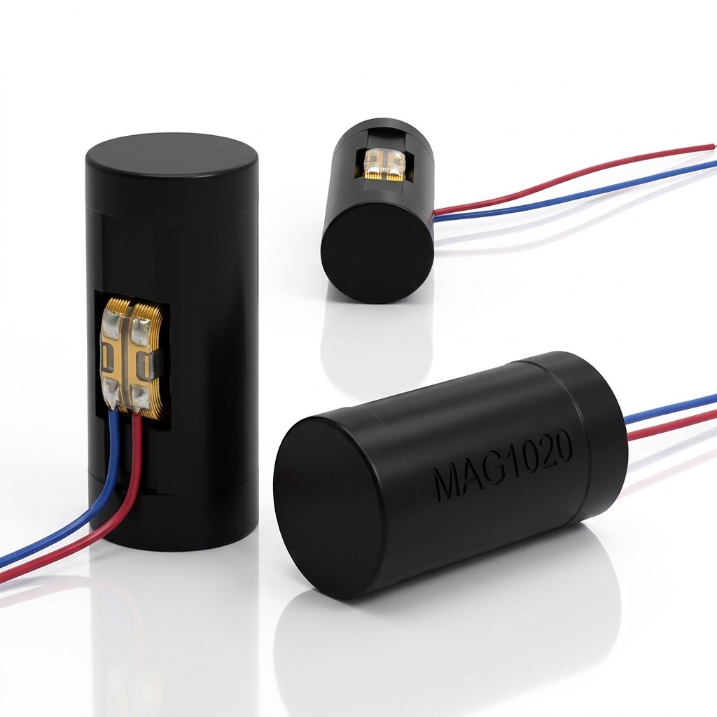
Linear magnetic rams are a close relative. They use magnetic levitation instead of a spring, so there's no friction between moving parts. INEED's MAG1020BEL40, for example, is rated at a 35 ms rise time, 50 ms fall time and 1.2 million cycles in a 2 s on / 1 s off duty cycle. Those are published figures for that one part — treat them as a sense of scale, not a rule for every linear magnetic device.
How piezo actuators work
Piezo actuators use the piezoelectric effect: the ceramic changes shape when you apply a voltage. Two layouts matter for haptics. Benders — unimorph or bimorph — bend a plate and give larger movement. Stacks move a tiny amount but are very stiff.
TDK's PowerHap is a multilayer piezo plate with copper inner electrodes. Titanium cymbals bonded to both faces act as levers, amplifying the plate's in-plane contraction by 15× in the z axis. TDK's PiezoHapt is a unimorph: a piezo element bonded to one side of a vibration plate. Some types are just 0.35 mm thick (the L8060 at 80 × 60 mm and the L3015 at 30 × 15 mm), designed to sit directly under a display.
TDK's published data for three PowerHap types shows the spread across the family:
Type | Dimensions (mm) | Rated voltage (V) | Expected acceleration* (g) | Max. force (N) | Max. displacement (µm) |
|---|---|---|---|---|---|
0909H011V060 | 9.0 × 9.0 × 1.1 | 0 to 60 | 2.5 | 5 | 35 |
1313H018V120 | 12.7 × 12.7 × 1.8 | 0 to 120 | 7 | 8 | 65 |
2626H023V120 | 26 × 26 × 2.3 | 0 to 120 | 35 | 25 | 230 |
*At a 100 g load. Source: TDK.
TDK's product brief also quotes a broader envelope for the whole portfolio: acceleration ≥ 50 g, force ≥ 50 N and displacement ≥ 280 µm. Those describe the best performers, not every part. The 1204H018V060 prototype datasheet gives a smaller, concrete example: 0.50 µF typical capacitance at 1 kHz, 27 µm displacement from 0 to 60 V, 43 µm from 0 to 95 V in overdrive mode, and a sensor output of 0.60 V/N.
What this means for feel
The two families create different control problems. An LRA or LMR is a resonant system. You shape the envelope of a sine wave at or near resonance; the driver has to find and hold that frequency, then brake out of phase to stop quickly. A piezo is closer to a displacement source. Its output is very linear — TDK quotes 1.8 µm/V for the 2626H023V120 — so you can command amplitude and waveform directly, as long as the driver can supply the charge its capacitance demands.
In practice, that shapes the feel. LMR and LRA effects work best as sustained buzzes and crisp clicks built from resonant sine bursts. Piezo effects can be shaped as any waveform — sine, triangle or rectangle — across a wide band. If your UX relies on short, sharp, high-definition taps, the piezo control model fits better. If it's mostly alerts and long buzzes on a tight power budget, LMR or LRA is usually easier to get right.
Performance and control bandwidth
Speed, latency and settling
TDK specifies a response time under 1 ms for PowerHap and 4 ms for the ultra-thin PiezoHapt. Those are component figures. System latency also includes driver startup, the host interface and effect scheduling. TI's DRV8662 piezo driver datasheet puts enable-to-output startup at typically 1.5 ms and recommends keeping total system latency under 30 ms so the response feels connected. That 30 ms line is a useful budget for any actuator family.
For LMR and LRA, latency is really about locking onto resonance and braking, not raw rise time. TI's auto-resonance engine locks onto the LRA frequency within half a cycle and tracks it cycle by cycle. With tracking on, TI's data shows a 56.0 ms start and 14.5 ms stop at 1.64 g, versus 51.7 ms start and 71.6 ms stop at 1.00 g with tracking off. The big difference is in stopping. Active braking — driving 180° out of phase at resonance — lets the LRA stop 75 ms faster than an unbraked waveform in TI's comparison. That settling behaviour, more than rise time, decides whether two quick clicks feel separate.
Force, movement and perceived strength
Perceived strength isn't one number. Piezo.com makes the point that you can express amplitude as acceleration, force or deflection, and that acceleration depends heavily on the mass being moved, plus damping and how the part is mounted. In their test, a 1.1 g accelerometer on a piezo tip measured hundreds of g. Recalculated for a 100 g mass, the same actuator peaked at about 3.5 g — in the same range as a typical LRA or ERM. A headline acceleration figure means nothing without its load. TDK's 2.5 g, 7 g and 35 g figures are all stated at 100 g load, so that's the condition to compare against.
Movement tells a different story. PowerHap's largest type reaches 230 µm, and the product brief quotes ≥ 280 µm across the portfolio. PiezoHapt's thin unimorph parts are built for bending a panel, not for large free movement. An LRA moves very little; its output is specified as acceleration at resonance. Which number predicts what users feel depends on the mechanical path. A rigidly coupled button passes force, a suspended panel passes movement, and a handheld device passes acceleration into the hand.
Waveforms and localization
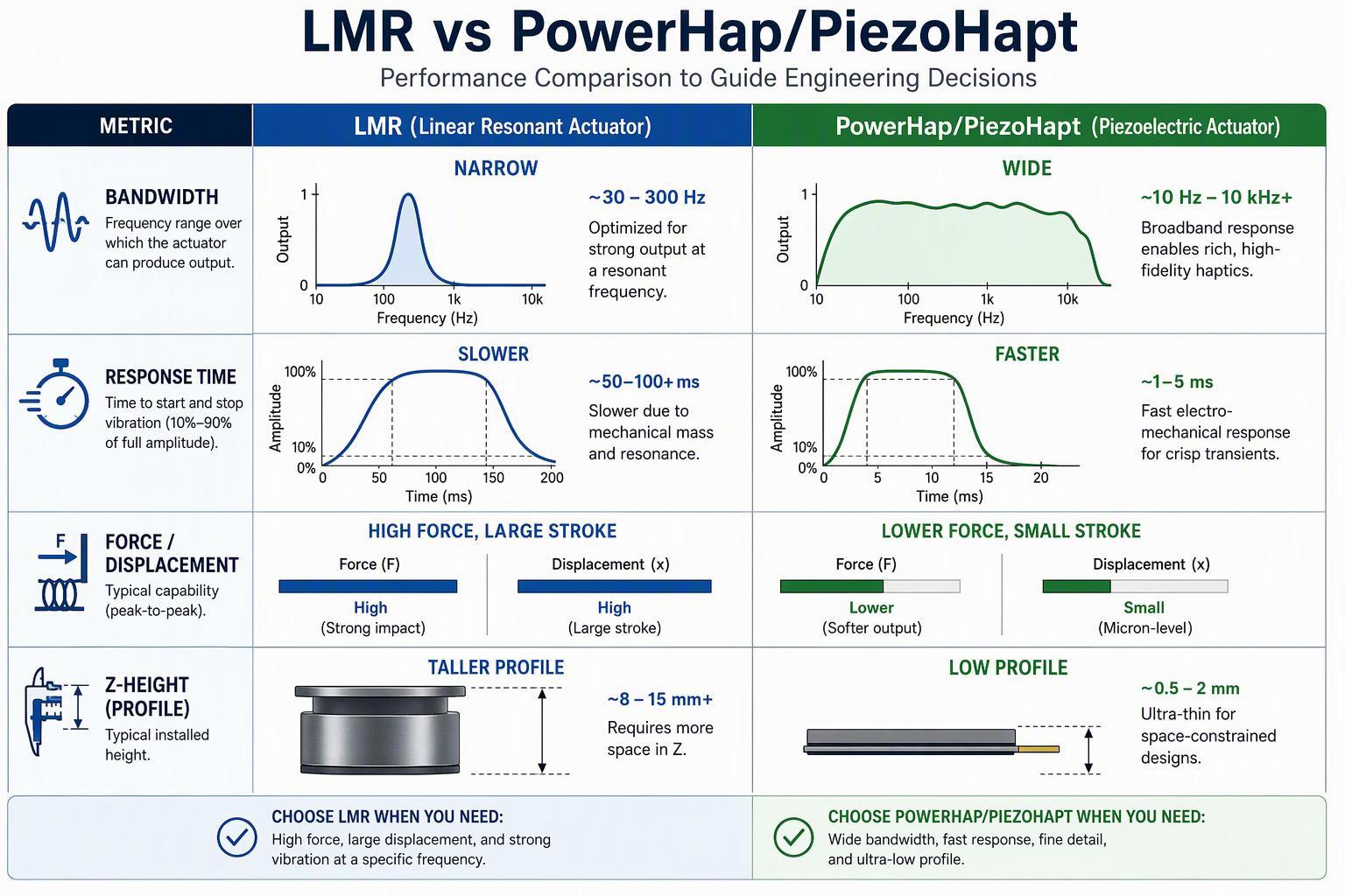
TDK says PowerHap can drive anything from 1 Hz to 500 Hz, with variable amplitude, duration and signal shape. That's what makes high-definition haptic profiles possible. LRA and LMR output sits near resonance, so the effect library is built from resonant bursts with envelope shaping, overdrive and braking.
Localization is a mechanical question as much as an electrical one. A piezo element under a display can bend the panel locally; an LRA in one corner shakes the whole enclosure. If your UX needs edge-localized feedback or different textures across a surface, piezo's waveform freedom and thin form factor make it easier to put the actuator where the motion should be. For a whole-device alert, LMR or LRA is simpler and cheaper to integrate.
Image brief: a comparison chart plotting bandwidth, response time, force/displacement and z-height for LMR versus PowerHap/PiezoHapt, with a caption stating that values are manufacturer-typical for specific part numbers and test loads, not interchangeable across parts.
Power and driver architecture
Every actuator family in this guide ends up in front of a driver, and for the resonant path that means a linear resonant actuator and its control loop. TI measured energy per click on three actuators at 5 V and a 100 g load, with peak acceleration held near 0.9 g. Click windows were 50 ms (ERM), 40 ms (LRA) and 19.61 ms (piezo). For sustained effects the ranking flips: in TI's phone-call scenario the piezo drew 140.2 µAh against 46.31 µAh for the LRA.
LMR and LRA drivers
These drivers are low-voltage and closed-loop. TI's DRV2605L, for example, runs from 2 V to 5.2 V, drives both ERM and LRA parts, and includes an auto-resonance engine that checks the actuator's back-EMF every cycle and adjusts the output as resonance moves. It also handles overdrive, braking, level calibration and diagnostics, and its overdrive clamp caps the peak voltage no matter which mode you use.
So the driver, not the actuator alone, decides whether the feel stays consistent. TI's lab comparison of 21 actuators, driven with and without auto-resonance, shows how much spread open-loop drive creates. If you're evaluating an LMR or LRA, test it with the driver you plan to ship, and check that its resonance tracking covers your temperature and mounting conditions.
Piezo drivers
Piezo drivers are boost converters paired with high-voltage amplifiers. TI's DRV8662 takes 3.3 V to 5.5 V, boosts the rail with an integrated DC-DC converter and drives capacitive loads with signals up to 200 Vpp, using one inductor and no transformer. Its recommended operating table ties load capacitance to boost voltage and frequency: 50 nF at 105 V and 500 Hz for 200 Vpp, up to 3 µF at 15 V and 300 Hz for 20 Vpp. That table sets your practical limit — a bigger or faster piezo needs more current than the driver can deliver.
TDK's evaluation kit for 60 V PowerHap parts uses the BOS1901 driver. It runs a differential output up to 190 Vpp full-scale, with DIP switches to cap the range at 60 V. The kit shows up as a USB audio device, so you can prototype waveforms in audio software. That's a good reminder: piezo haptics is often prototyped with audio tools.
Energy per click depends on the effect. TI measures 0.34 µAh per click for piezo, 0.58 µAh for LRA and 1.72 µAh for ERM, with the piezo click lasting 19.61 ms against 40 ms for the LRA. But the phone scenario shows this ranking isn't universal: longer, constant-acceleration effects suit the resonant actuator. The honest read is that piezo wins on short transients and LRA wins on sustained effects — and your product's mix of effects decides the energy budget.
EMC, discharge and safety
Two safety points apply only to piezo. First, TDK warns that piezo parts are efficient charge-storing capacitors. Even unplugged, a loaded actuator can hold significant energy for a long time. Discharge it fully before handling — for example through a 10 kΩ resistor, not a simple short, which can damage the ceramic. Second, high-voltage driver rails need care in layout and test. TDK's evaluation-kit note carries a high-voltage warning and recommends isolated test gear with overvoltage and overcurrent protection.
On EMC, treat the piezo driver's boost converter as what it is: a switching supply. Lay it out and filter it accordingly, using the DRV8662 layout guidance and the DRV2605L decoupling recommendations as starting points. For medical products, the EMC collateral standard is IEC 60601-1-2, which the FDA recognises in its standards database. LMR and LRA drivers are low-voltage switching outputs and are usually easier to keep quiet, but their back-EMF sensing and PWM edges still need attention.
Mechanical integration and tolerances
Here's how tall representative parts are, based on manufacturer datasheets and product pages. PiezoHapt's L3015 is quoted at 0.3 mm in TDK's application article, and 0.35 mm for the L8060; PowerHap heights cover the three published square types. LRA heights are INEED's 6 mm and 8 mm coin parts. Height alone doesn't predict feel — panel coupling and mounting decide what reaches the user.
The table below shows what an actual LRA family looks like on paper. All five parts are INEED catalogue models, from the 6 mm coin up to the 20 × 24 mm brick used in game controllers.
Model | Size (mm) | Rated voltage | Frequency | Rise / fall | Acceleration | Typical use |
|---|---|---|---|---|---|---|
LRA0625BC03L28 | ⌀6.0 × 2.5 | 0.7 Vrms AC | 260 H ± 10 | ≤50 / ≤80 ms | 0.7 Grms | Phones, touchscreens |
LRA0825BC03L45 | ⌀8.0 × 2.5 | 1.2 Vrms AC | 240 Hz ± 10 | ≤50 / ≤80 ms | 0.7 Grms | Handhelds, wearables |
LRA0832BC03L27 | ⌀8.0 × 3.25 | 1.8 Vrms AC | 235 Hz ± 10 | ≤50 / ≤80 ms | 1.0 Grms | High-reliability consumer devices |
LRA2024AYL80 | ⌀20 × 24 | 1.2 Vrms AC | 65 Hz ± 10 | ≤55 / ≤80 ms | 2.5 Gp-p | Game controllers, VR, automotive |
MAG1020AYL40 | ⌀10 × 20 | 1.2 Vrms AC | 150 Hz ± 10 | ≤35 / ≤50 ms | 2.0 Gp-p | HD haptics, broadband LMR |
Two things stand out. Every part vibrates on the Z axis, perpendicular to the motor face, so the mounting direction is fixed by the design. And the smallest model is also the lowest voltage at 0.7 Vrms, which matters on a tight supply rail. Note that acceleration is quoted as Grms on the coin parts and Gp-p on the larger blocks — different measurement conventions, so don't compare those numbers directly.
The LRA2024AYL80 electrical motor is the outlier in the family. Its 65 Hz resonance makes it feel slower and heavier, which is exactly what you want under a controller grip rather than under a phone screen.
Mounting, preload and adhesives
Piezo parts mount with adhesive and are sensitive to tolerance. TDK's 1204 datasheet recommends bonding the actuator to contact surfaces on both sides, notes that double-sided pressure-sensitive tape often works, and points out that tape thickness variation can help you tune height. The same datasheet limits compressive force to 10 N during operation and short-term impact force to 80 N. Treat those as hard limits when you design clamps, covers and assembly fixtures.
LMR and LRA mounting is a spring-mass problem. The resonant frequency depends on how the part is held, so the bracket, foam and housing are part of the resonator. TI lists mounting and device position — gripped tightly versus sitting on a table — as causes of frequency drift. A mount that's stiff one way and soft another will feel different depending on how the user holds the product.
Z-height, panel coupling and resonance drift
Z-height is where piezo clearly wins at the thin end: PiezoHapt parts at 0.35 mm and PowerHap from 1.1 mm to 2.3 mm, against LRAs at about 2.5 mm and up. If the stack has no room for a coin motor plus bracket, piezo may be the only option that fits.
Panel coupling changes the picture. A piezo bonded to a display bends that panel and can sit directly beneath flat surfaces, which TDK notes allows highly leak-tight designs — useful in harsh industrial or hygiene-sensitive settings. An LRA shakes the whole enclosure through its mount. Neither is universally better; it comes down to whether your UX wants local panel motion or whole-device vibration.
Resonance drift is the LMR/LRA tax. TI lists manufacturing tolerance, aging, temperature, mounting and grip as causes. Industry tuning guidance puts LRA drift at roughly −0.2 Hz/°C, which closed-loop back-EMF tracking handles and open-loop drive doesn't. Piezo movement is far more linear with voltage, but its capacitance and self-heating still shift with temperature and drive level, so respect the driver's voltage and current limits across the full operating range.
Validating at EVT and DVT
Test what the user feels, in the assembly you plan to ship. A practical measurement kit:
Accelerometer on the touch surface, with the device held in the intended grip and resting on the intended surface, since both change the reading.
Laser vibrometer or displacement probe for piezo designs that bend a panel, where movement rather than acceleration is the design metric.
Current probe and supply logging to capture energy per click and confirm the boost stage stays within its load-capacitance limits.
Thermocouples on the actuator and driver during sustained effects, because piezo self-heating caps continuous operation.
Frequency sweep to map the assembled resonance for LMR or LRA and confirm the driver tracks it across temperature.
INEED Electronics supports this stage with custom electrical parameters, connectors, lead wires and housing, plus in-house help with haptic integration and tuning. For teams that need to test an LMR or LRA in their own stack, INEED's rapid prototyping service ships working samples in as little as five days, which shortens the loop between a failed DVT measurement and a revised part.
Reliability, environment and compliance
Failure modes and lifetime
The failure modes differ by family. With piezo, the ceramic is brittle, and the datasheet limits are your protection. Push past the maximum compressive or impact force, drive beyond rated voltage outside the defined overdrive conditions, or mishandle a charged part, and you can crack or depole the element. TDK's 1204 datasheet allows 0 to 95 V in overdrive mode for up to two consecutive cycles, repeatable with at least 100 ms between them. That's a precise statement of what overdrive is — and a warning not to treat it as a continuous operating point. The same datasheet limits frequency by self-heating, which must not exceed +30 °C; that's reached after about 10 s of continuous sine at 0 to 60 V and 700 Hz.
For LMR and LRA, the wear items are the spring, bearing surfaces and coil. Lifetime is usually quoted in cycles under a defined drive and duty cycle. INEED's MAG1020BEL40, for example, is rated at 1.2 million cycles in a 2 s on / 1 s off mode. Compare that to another actuator only if drive level and duty cycle match.
Piezo lifetime data exists, but read the conditions. PI reports that preloaded PICMA multilayer actuators running 120 V unipolar sine at 1157 Hz showed no failure after 10¹⁰ cycles, and that NASA tests found 96% of original movement after 10¹¹ cycles. Those results are for PI's parts under those conditions. They show multilayer piezo can last a long time — not that any piezo part will.
Environment and shock
TDK's 1204 datasheet rates operating temperature at −40 to +85 °C powered and −40 to +125 °C unpowered, with a maximum short-term impact force of 80 N. Design your housing and drop spec around those numbers. For LMR and LRA, INEED's published specs vary by part: its LRA0832BC03L27 linear motor is rated −20 to +60 °C at 65 ± 20% RH with storage to +70 °C, while supplied coin-motor specs use 10–90% RH and include a type rated to +70 °C in operation. Check the exact part; limits differ across the catalogue.
Test shock and drop separately. A piezo element takes drop energy through its bond line and cymbals; an LRA takes it through its spring and end stops. Run the test on the final stack in both cases, because the housing and panel change how much energy reaches the actuator.
Rules for medical and consumer devices
For medical devices, the general safety standard is IEC 60601-1 and the EMC collateral standard is IEC 60601-1-2, which the FDA recognises in its standards database with a partial recognition that excludes specific clauses. IEC 60601-1 is large and is modified by collateral and particular standards, so don't apply it alone. For a haptic actuator, the practical hooks are the EMC requirements of 60601-1-2, the mechanical safety and risk-management requirements of 60601-1, and the biocompatibility and cleaning requirements that come from the device's intended use. That last one is where a sealed, panel-bonded piezo design can simplify your case.
For consumer devices, check the EMC and safety rules of your destination market, plus the material declarations your supplier provides. INEED's specifications state compliance with EU 2005/618/EC for the relevant parts. That's a supplier declaration — verify it against your own regulatory plan rather than treating it as a substitute.
Selection heuristics and risk management
Choosing between LMR and piezo
The decision usually comes down to four questions, in this order:
Does the UX need arbitrary waveforms or wideband effects? If yes, go piezo. If the library is clicks, alerts and buzzes, LMR or LRA is enough — and simpler.
Is there room for a boost stage and a high-voltage layout? If not, LMR or LRA. If yes, piezo is on the table.
Is the stack thinner than about 2.5 mm at the actuator? If so, piezo's 0.35 mm to 2.3 mm parts may be the only ones that fit.
Is the main effect short or sustained? Short transients favour piezo on energy; sustained effects favour LRA.
A sensible default: use LMR or LRA for cost-sensitive, battery-powered alerting with a simple effect library and room in the stack. Use piezo when the UX depends on high-definition, localized or wideband feedback, or when z-height is the binding constraint.
Drivers and second sourcing
The driver is part of the actuator decision. LMR and LRA drivers are low-voltage and available from multiple vendors, which makes sourcing easy. Piezo drivers are fewer — TI's DRV8662 and Boreas' BOS1901 are the usual names — and the boost stage adds magnetics and high-voltage capacitors to the BOM. Second-sourcing a piezo actuator is also harder than an LRA, because the mechanical interface, capacitance and voltage rating are part-specific. A drop-in swap usually means a driver re-tune and a re-validation.
On the actuator side, LMR and LRA supply is broad. Many manufacturers offer standard coin and linear parts, plus custom leads, connectors and housing. INEED Electronics, for example, lists LRA parts from 6 mm to 8 mm diameter plus a linear magnetic actuator — the 6 mm coin is the smallest unit in the 6mm linear resonant actuator range — with customization of electrical parameters, connectors, lead wires and housing, backed by more than 20 automated production lines. For a program that needs a second source or a custom lead at ramp, that breadth matters.
Risk checklist
Use this checklist at the design review before committing to a family:
Effect library defined, with the longest and shortest effects listed and their energy per click estimated.
Latency budget written down, including host interface, driver startup and actuator rise, against a 30 ms perceptibility threshold.
Z-height and footprint allocated in the mechanical stack, including adhesive and tolerance.
Driver selected and its load-capacitance or resonance-tracking limits checked against the chosen actuator.
High-voltage handling, discharge procedure and EMC plan documented (piezo) or back-EMF sensing and PWM layout reviewed (LMR/LRA).
In-system measurement plan agreed: accelerometer, displacement probe, current logging and thermocouples.
Environmental and shock limits taken from the specific datasheet, not the family headline.
Regulatory hooks identified for the destination market, with supplier declarations collected.
Second-source and lead-time plan agreed with sourcing.
Run the verification in this order: bench characterisation of the actuator alone, then in the EVT stack, then in the DVT assembly with the final housing and panel. Each stage should reproduce the previous stage's key metric within a stated tolerance, or the difference should be explained.
FAQ
Which is cheaper to build into a product, LMR or piezo?
LMR and LRA usually cost less in total. The actuator is widely available, and the driver is a low-voltage part you can source from several vendors. Piezo needs a boost stage, high-voltage capacitors and a more careful layout, so the BOM and the engineering effort both grow. But cost only decides the answer when the feel requirements are modest. If your UX depends on sharp, high-definition taps or a very thin stack, piezo can be the cheaper route to a shippable product, even at a higher part cost.
Can I drive a piezo actuator from a battery-powered device?
Yes. The boost converter sits between the battery and the actuator, so a 3.3 V to 5.5 V rail is enough input. The real constraint is current. Your driver has a load-capacitance limit at a given voltage and frequency, and a larger or faster piezo will exceed it. Check that table before you commit.
How long will a haptic actuator last in a wearable or medical device?
It depends on the part and the drive. LMR and LRA lifetime is quoted in cycles at a defined duty cycle — INEED's MAG1020BEL40, for instance, is rated at 1.2 million cycles in a 2 s on / 1 s off mode, and the 8mm small linear resonant actuators are quoted on the same 2 s on / 1 s off basis. Piezo parts can reach very high cycle counts when driven within their limits, but that data only applies to the exact conditions tested. Compare lifetime figures only when the drive level and duty cycle match.
Why does my haptic feedback feel different between units?
On LMR and LRA designs, it's almost always resonance. The resonant frequency shifts with part tolerance, temperature, aging and how the actuator is mounted, so open-loop drive produces a spread. Closed-loop drivers that track back-EMF fix most of it. On piezo designs, look at mounting first: adhesive thickness, preload and bond-line voids change how much motion reaches the panel. Either way, measure several units in the final assembly, not one unit on a bench.
Do I need to change my actuator if I move from a prototype to mass production?
Not necessarily, but you should re-validate. Small changes in housing, adhesive or panel material can shift the feel. A supplier that offers customization of leads, connectors and housing — and fast sample turnaround — makes that transition easier. INEED, for example, ships working samples in as little as five days, which keeps the loop short when a DVT measurement falls short.
Conclusion
The question isn't "piezo is better" or "LMR is better." It's which control problem your team can solve within the program's constraints.
LMR and LRA actuators are low-voltage, easy to source and efficient for sustained effects. Their feel depends on resonance tracking, which you must validate across temperature, mounting and unit spread. Piezo actuators like PowerHap and PiezoHapt give sub-millisecond response, wideband arbitrary waveforms and very low z-height. In return, they need a boost stage, a capacitive-load design, high-voltage handling and a stack that protects a brittle ceramic.
Four habits decide most outcomes: measure in the final assembly, not on the bench; read every acceleration figure with its load; treat overdrive and self-heating limits as hard constraints; and budget latency end to end against the roughly 30 ms line.
Next steps. Pull the datasheets for your candidate parts — TDK's PowerHap and PiezoHapt for the piezo path, and the LMR or LRA supplier's spec for the linear path — and check voltage, force, temperature and lifetime against your requirements. Choose the driver based on the actuator's load model, not the other way round. Then build a prototype and validate it in-system against the standards for your market before you commit to tooling. Final performance belongs to the assembled product, and only in-system testing can confirm it.