Tuning Vibration Frequency vs Duty Cycle for Haptic Fidelity
How duty cycle and frequency interact on ERM and LRA actuators, plus resonance tracking, braking, and how to measure haptic fidelity.
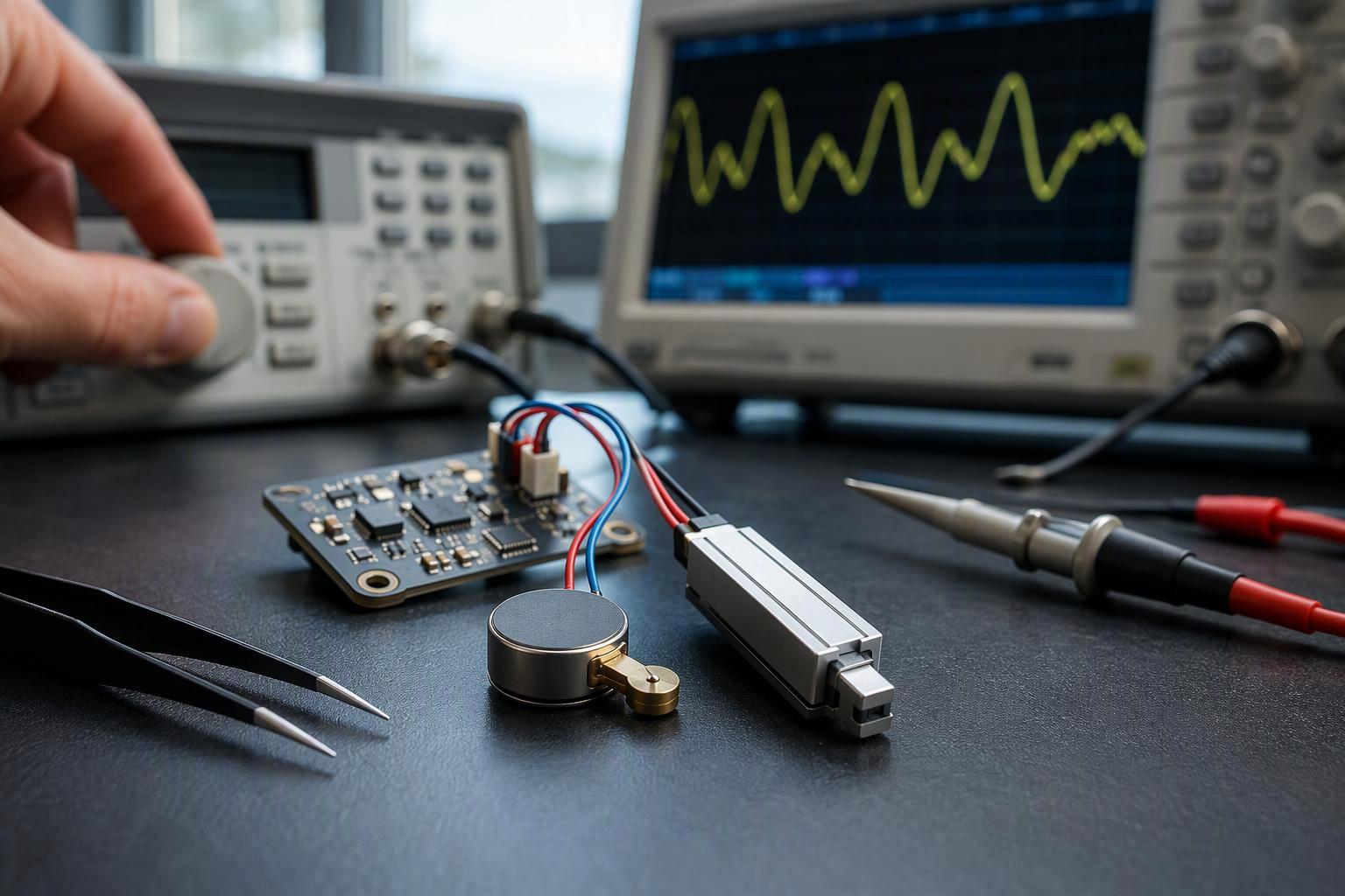
Vibration frequency vs duty cycle is the first control decision an engineer makes when specifying a haptic actuator, and it is also the one most often made by default. An ERM takes a simple DC voltage or PWM signal, and in the PWM case the duty cycle is proportional to vibration strength (TI's haptic implementation guide, rev. A, read 2026). An LRA takes an AC drive and has a narrow operating bandwidth centered on that resonance, so amplitude modulation is easy but frequency must track the resonance (TI's ERM vs LRA overview, read 2026). Those two sentences describe different control problems, not two settings of the same knob. For a side-by-side breakdown of the actuators themselves, see the ERM vs LRA comparison for engineers.
The energy argument for the second path is measurable. At VDD = 5 V and peak acceleration held near 0.9 g, an ERM click drew 124 mA over 50 ms for 1.72 µAh, while an LRA click drew 52.6 mA over 40 ms for 0.58 µAh, so the LRA gives 67% energy savings per click (TI's haptic energy consumption report, rev. current, read 2026). That figure holds only when the LRA is actually driven at resonance, which is the whole engineering problem.
This guide compares the two control paths criterion by criterion: how duty cycle and frequency interact on each actuator, what the driver IC does for you, how the resulting feel differs on a wrist versus a fingertip, how to measure haptic fidelity repeatably, and what integration and compliance work remains. The verdict belongs at the end, because which path fits depends on the effect you are shipping.
Key Takeaways
On an ERM, duty cycle sets strength and frequency follows from it, so the two cues cannot be tuned independently.
On an LRA, duty cycle sets amplitude and the driver IC sets frequency, which is why resonance tracking is a requirement rather than a feature.
An LRA saves 67% energy per click versus an ERM at equal acceleration, but only when driven within roughly ±2 Hz of resonance.
Braking is what separates a crisp click from a buzzy one, and it requires a differential output stage on either actuator type.
Validate with an EVT/DVT matrix that sweeps frequency, duty, temperature, and mounting, because resonance drifts with all four.
ERM control fundamentals
An ERM is a brushed DC motor with an offset mass, and its control model boils down to one variable. The duty cycle of a PWM drive sets average voltage, average voltage sets speed, and speed sets vibration frequency. The coupling is direct: raise the voltage and the shaft spins faster, so both frequency and vibration force rise together. A coin ERM, for instance, runs at 8,000 rpm or higher, and spinning the offset mass at different speeds is what produces different vibration frequencies and intensities (INEED's ERM vibration motor overview, 2026). You cannot raise strength without raising frequency, and that linked behavior is what gives an ERM its characteristic feel.
Key Takeaway: On an ERM, duty cycle is not a strength knob on its own. Every change in drive voltage moves frequency and amplitude together, so plan the effect around the coupled pair rather than around intensity alone.
Duty cycle, average voltage, and speed (RPM)
The practical consequence is that a duty-cycle ramp is also a frequency ramp. If your effect calls for a soft tap followed by a strong buzz, the tap arrives at a lower frequency than the buzz, and the user feels a pitch change as well as a strength change. ERMs also have a minimum voltage below which the shaft won't turn at all, so the bottom of your duty range is a dead zone rather than a gentle minimum. INEED's cylindrical ERMs, for example, cover a 1.3 V to 4.5 V DC range, and the low end of that window has to be respected if the motor is to start reliably (INEED's ERM vibration motor overview, 2026). For the underlying motor behavior behind these limits, see ERM vibration motor characteristics.
PWM carrier selection and ripple effects
The PWM carrier is a separate setting from the duty cycle that sets strength, and it has its own limits. The DRV2603 accepts a PWM input from 10 kHz to 250 kHz and generates an internal PWM output between 19.5 kHz and 21.5 kHz (20.3 kHz typical) (the DRV2603 datasheet, rev. current, read 2026). Keeping that carrier above the audible band matters in a wearable pressed against the wrist, and the motor winding resists fast current reversal, which is why coreless and coin motors handle PWM drive more gracefully than larger framed motors.
The mapping from duty to output isn't always linear, and the driver's mode changes it. In open-loop ERM mode on the DRV2604L, output voltage follows PWM duty cycle with OD_CLAMP as full scale: 0% gives 0 V, 50% gives 0 V at mid-scale with no drive, and 100% gives OD_CLAMP, while anything below mid-scale produces negative drive for counter-rotation or braking (the DRV2604L datasheet, rev. current, read 2026). In closed-loop unidirectional mode the same pin maps 0% to 0x00, 50% to 0x7F, and 100% to 0xFF, with steady-state magnitude set by RATED_VOLTAGE. Build your duty table around the mode you actually configure, because the midpoint means opposite things in the two cases.
Startup, overdrive, and active braking
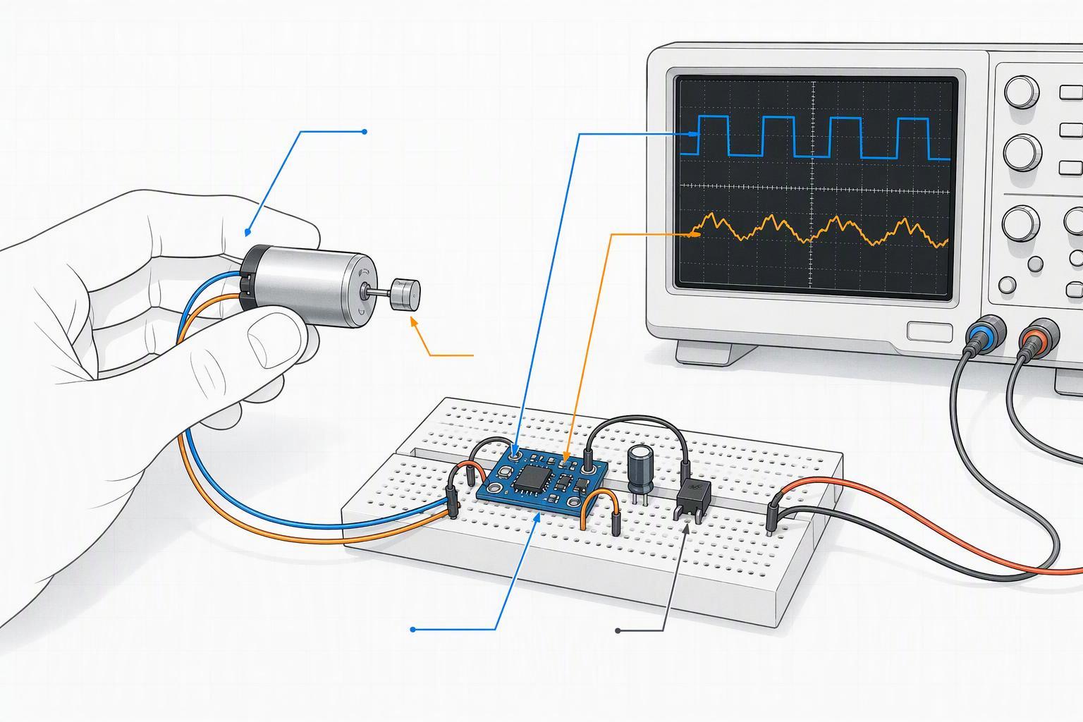
Start and stop times drive perceived crispness, and both are tunable. Overdrive means applying a voltage higher than steady state for a short burst to cut start-time and brake-time, and a closed-loop system can overdrive automatically and adjust as the actuator changes (TI's haptic implementation guide, rev. A, read 2026). The DRV2605L exposes this through selectable ERM libraries: library A gives 40–60 ms rise and 20–40 ms brake, library B gives 40–60 ms and 5–15 ms, library D gives 100–140 ms and 15–25 ms, and library F, run at 4.5 V and 5 V overdrive, gives 35–45 ms rise and 10–20 ms brake (the DRV2605L datasheet, rev. current, read 2026). A measured example shows the same result: an NRS2571i ERM driven by a DRV2605 at VBAT = 3.6 V started in 47 ms and braked in 37 ms (TI's haptic implementation guide, rev. A, read 2026).
Without braking, the actuator keeps vibrating until mechanical damping brings it to rest, which can take hundreds of milliseconds (TI's haptic implementation guide, rev. A, read 2026). Braking an ERM means applying voltage in the opposite direction, so a typical single-FET drive can't do it. You need an H-bridge or a differential output stage, such as the DRV8601, DRV2603, DRV2604, DRV2605, DRV2605L, DRV2624, or DRV2625 (TI's haptic implementation guide, rev. A, read 2026). Reversing the DC polarity this way shortens the stop time and sharpens the effect.
LRA control fundamentals
An LRA is a spring-mass system driven by a voice coil, and its control model splits into two independent variables. Amplitude is set by the drive envelope, and frequency must match the mechanical resonance, which is why the two cannot be treated as interchangeable with an ERM. TI's actuator primer describes an LRA as an AC-driven device, roughly 2 Vrms, whose resonant frequency is set by spring and mass and whose operating bandwidth is narrow around that point: amplitude modulation is easy, but frequency must track resonance (TI, Haptics: Solutions for ERM and LRA Actuators, read 2026). The usable band is tight enough to be a design constraint rather than a footnote. TI's energy report states an LRA must be driven within about ±2 Hz of resonance for noticeable vibration (TI's haptic energy consumption report, rev. current, read 2026).
Resonance, frequency locking, and amplitude control
Resonance values are actuator-specific, so they belong in the datasheet review rather than in an assumption. Compact LRAs commonly resonate somewhere between roughly 65 Hz and 260 Hz. An 8 mm LRA such as the LRA0832BC03L27 sits at a 235 Hz F0 with acceleration of at least 1.0 Grms, while a wideband actuator anchors the other end of the scale: the LRA2024A series is rated at 65 ±10 Hz with an effective bandwidth of 30–500 Hz, 1.2 Vrms AC, 200 mA maximum, acceleration of at least 2.5 Gp-p at F0, rise time of 55 ms or less, fall time of 80 ms or less, and 1,000,000 cycles at 2 s on and 1 s off (INEED's linear resonant actuator page, 2026).
That last specification exposes a driver-selection trap. The DRV2605L datasheet states an LRA frequency range of 125 Hz to 300 Hz, with the minimum raised from 50 Hz in a revision (the DRV2605L datasheet, rev. current, read 2026). A 65 Hz actuator sits below the range that driver states it supports, so verify any pairing against the driver's recommended operating conditions before committing to a bill of materials. For a fuller treatment of coil, suspension, and driver matching, the LRA design and integration guide walks through the mechanical side of the same problem.
Auto-resonance tracking and driver IC features
Auto-resonance tracking is what makes a narrow-band actuator practical. The driver senses the LRA's back-EMF on the output pins every cycle and feeds it to the auto-resonance engine; if the frequency is too high it lowers the output frequency, and if too low it raises it (TI's auto-resonance tracking note, rev. A, read 2026). Tracking ranges differ by device and should not be generalized across a family: the DRV2603 tracks 140 Hz to 220 Hz and starts in 1.3 ms typical from enable high to output (the DRV2603 datasheet, rev. current, read 2026), while the DRV2625 acts over 45 Hz to 300 Hz (TI's auto-resonance tracking note, rev. A, read 2026).
Pro Tip: Match the driver's tracking range to the actuator's rated frequency before layout. A 65 Hz LRA and a 235 Hz LRA can need different driver parts, and the range is fixed in silicon, not configurable in firmware.
Why not low-frequency PWM directly on the coil
You can't simply drive an LRA coil with a low-frequency PWM signal, because the driver already separates the two control variables. The PWM input to the driver is a filtered DC level that represents the waveform envelope or amplitude, while the driver generates the sine wave output at the detected resonant frequency (TI's auto-resonance tracking note, rev. A, read 2026). Duty cycle sets amplitude; the driver sets frequency. Remove that split and you're trying to build an AC waveform from a DC source, and the actuator's narrow band punishes any error in the resulting frequency. INEED makes the same point in its own drive guidance: an LRA needs an AC waveform near F0 plus a driver IC, and it cannot run directly from a DC battery voltage (INEED's linear resonant actuator page, 2026).
On the braking side, the driver applies a waveform roughly 180° out of phase with the actuator motion, and with resonance tracking it can drive vibration to zero without the reverse-phase vibration an ERM can produce (the DRV2603 datasheet, rev. current, read 2026).
Frequency, duty, and perceived feel
Perceived fidelity is a timing problem before it is an amplitude problem. Android's haptics design principles say a good keyclick should last 10 to 20 ms, but the actuator may keep ringing for another 20 to 50 ms after a 20 ms input ends. That's why the platform advises against legacy one-shot vibrations for this kind of feedback (Android's haptics design principles, current docs, read 2026). The gap between the signal you send and the response the user feels is where vibration frequency vs duty cycle stops being a driver setting and becomes a design decision.
Amplitude vs frequency cues on wrist vs fingertip
The two control paths produce different cue structures, and the difference matters more on a fingertip than on a wrist. On an ERM, duty cycle is proportional to vibration strength, so a strength ramp is also a frequency ramp: the user reads the change as both stronger and higher-pitched (TI, Haptic Implementation Considerations, rev. A, read 2026). On an LRA, amplitude and frequency are independent, which is what allows a richer waveform and a more expressive effect. Android draws the same distinction from the application side: clear haptics are crisp and discrete, while rich haptics usually need actuators with a wider frequency bandwidth and can also be built by sequencing clear primitives at varied amplitudes and intervals (Android's haptics design principles, current docs, read 2026). A fingertip picks up short, high-frequency detail that a wrist misses, so an effect tuned on a wrist-mounted prototype will feel softer and less distinct once it moves to a handheld or finger-contacting surface.
Envelope shaping: attack, plateau, decay
Envelope shaping is where duty and frequency stop being settings and become a waveform. The attack is the overdrive window, the plateau is the steady-state drive, and the decay is the braking window, and each one has a driver-level control. On the ERM side, a long plateau with a slow decay is exactly the shape that produces the ringing Android warns about, so the decay window is the lever that decides whether a click feels crisp or buzzy.
⚠️ Warning: A one-shot vibration does not stop when the input stops. If the decay window is left long, the actuator keeps ringing for 20 to 50 ms past the command, and the effect the user feels is the tail, not the click.
Coding patterns: bursts, gaps, and intensity
Coding patterns are built from the primitives above. Android's guidance is to tie event importance and frequency to strength, keeping effects on very frequent events like scrolling subtle, and to combine concepts so effects build as an interaction nears a target — for example, gradually increasing the amplitude of a sequence of ticks during a drag, drop, or snap (Android's haptics design principles, current docs, read 2026). On an ERM, each burst in the pattern carries its own frequency because duty sets both, so a rising-intensity pattern also rises in pitch. On an LRA, the pattern can hold frequency steady while amplitude varies, which is the cleaner way to encode intensity without adding a pitch cue the designer didn't intend.
Measurement and validation
Haptic fidelity measurement starts with one choice that shapes everything downstream: what the transducer is attached to. An accelerometer bonded to the enclosure captures what the user actually feels, while one mounted on the actuator captures what the driver produces. Those two readings pull apart as soon as mounting mass and grip change, so a bench figure taken with the device clamped in a fixture is a starting point, not a final answer. Plan the measurement chain as carefully as the drive chain, and record the mounting condition next to every number you keep.
Accelerometer placement and sampling/FFT
Sampling rate and FFT window length trade off against each other, and the effect you're characterizing sets that trade-off. A 10 to 20 ms keyclick is short enough that a long FFT window smears attack and decay into one averaged spectrum, which throws away the envelope information that decides perceived crispness. A short window keeps the envelope but gives coarse frequency resolution, and that matters when the quantity you need to resolve is the narrow usable band around resonance. Capture the time-domain acceleration waveform for envelope work and the spectrum for resonance work. One window setting won't serve both, so set up two acquisition profiles and label which one produced each result.
Back-EMF sensing and calibration limits
Back-EMF is the electrical proxy for mechanical motion. It's useful, and it's not a substitute for an accelerometer. The driver senses the LRA's back-EMF on the output pins every cycle and uses it to determine frequency, so the tracking signal is observable. On the DRV260x and DRV262x families, a register holding an LRA_PERIOD byte can be translated with the datasheet formula to report operating frequency. What back-EMF can't tell you is the acceleration the user feels, because it's measured at the drive electrodes rather than at the enclosure surface. Treat it as a frequency and health indicator, and calibrate amplitude against a physical accelerometer.
EVT/DVT test matrices and tolerance analysis
Run the matrix at engineering validation and repeat it at design validation. Build it around four axes: drive frequency across the actuator's stated band, duty cycle across the usable amplitude range, temperature across the product's operating range, and mounting condition across the ways the product is actually held. Unit-to-unit variation is the expected case, not the exception, so size the tolerance analysis to the worst-case unit instead of the golden sample. When you need datasheet values, customization options, or rapid samples to fill out the matrix, INEED Electronics publishes motor specifications and offers rapid-sample turnaround.
Key Takeaway: Validate at EVT to find the drift axes, then repeat at DVT to confirm the worst-case unit still meets the specification. A matrix that only ever tests the golden sample proves nothing about production.
Where the evidence stops: published application notes describe what causes resonance drift, but they don't prescribe a sampling rate, window length, or matrix size for a given product. Those numbers come from your own actuator, your own enclosure, and your own tolerance budget. Pick starting values, document them, and revise them once the first DVT run shows which axis dominates.
System integration and compliance
Integration starts with the power budget, because vibration strength follows the driving signal, and the supply sets the ceiling on what the actuator can deliver. A differential output stage is recommended for LRA actuators to get the most vibration strength out of them; a single-ended solution running from a typical Li-Ion battery is capped at the battery voltage, which makes certain waveforms impossible (TI's haptic implementation guide, rev. A, read 2026). If your effect library assumes a differential swing, a single-ended supply will quietly cap it. The wider integration picture, from driver selection to mechanical mounting, is covered in these haptic motor integration best practices.
Power headroom, inrush, and thermal limits
Inrush is the other half of the power story. Overdrive deliberately applies a voltage higher than steady state for a short period, and that transient comes off the same rail as the rest of the system, so the supply and its decoupling have to be sized for the peak rather than the average. The energy figures give you the average to plan against: at VDD = 5 V, an ERM click consumed 1.72 µAh and an LRA click 0.58 µAh — a 67% energy saving per click for the LRA (TI's haptic energy consumption report, rev. current, read 2026). The same document qualifies that ranking by effect duration: the piezo uses the least energy on short effects, the LRA is the best actuator for long-duration effects, and the ERM and piezo draw nearly the same current per g in long effects. A blanket efficiency ranking would misstate the source. Thermal limits follow from the same duty pattern: a motor driven at high duty for long bursts heats faster than the average current suggests, so derate against the worst sustained burst in your effect library, not the average.
Warning: Size the rail and decoupling for the overdrive peak, not the average click current. An under-sized bulk capacitor shows up as a brownout on the display or radio during haptic bursts, and it will not appear in bench tests that fire single clicks.
EMI/EMC layout, grounding, and switching strategy
The switching strategy is an EMC decision as much as a control decision. The DRV2603's internal PWM output runs between 19.5 kHz and 21.5 kHz (20.3 kHz typical), and its PWM input accepts 10 kHz to 250 kHz (the DRV2603 datasheet, rev. current, read 2026), so the carrier and its harmonics sit in a band you have to keep out of sensitive analog and RF paths. Keep the actuator return current on a short, wide path back to the driver ground, and treat the differential output pair as a loop whose area you're trying to minimize. The motor leads are part of the antenna themselves, so lead length and routing belong in the layout review rather than the mechanical drawing. Where the actuator sits near sensitive circuitry, the choice between encapsulated and enclosed vibration motors also affects shielding and grounding options.
Safety, environmental, and reliability testing
Write reliability requirements into the component specification before the first prototype, because they decide what the supplier has to demonstrate. A published example sets the post-durability acceptance criteria at initial acceleration within ±10%, rated current within ±30%, frequency within ±10 Hz, and noise below 50 dB(A), with environmental testing that includes temperature shock cycling between −40 °C and 85 °C and performance checks after the test (INEED's published reliability requirements, 2026). The same source advises operating within the stated voltage range, using motors within six months of delivery, and avoiding high-damp, high-temperature, corrosive gas, and rusty metal environments. Cycle life belongs in the same specification: the LRA2024A series is rated for 1,000,000 cycles at 2 s on and 1 s off (INEED's linear resonant actuator page, 2026), and that duty profile should be compared against your actual usage pattern rather than assumed to cover it.
Conclusion
The choice between the two control paths follows from what you need the actuator to do. Pick an ERM when the effect is a simple alert or notification, when cost and driver simplicity matter most, and when a linked frequency and amplitude response is acceptable or even useful. Pick an LRA when the effect is a crisp click, a textured drag, or a long-duration buzz, when energy per effect matters, and when you're willing to take on resonance tracking as a design requirement. The 67% energy savings per click is real but conditional on driving at resonance, and the ±2 Hz usable band is what makes that condition demanding.
Whichever path you take, three integration decisions decide whether the result survives contact with production. First, check the driver and actuator pairing against the driver's stated frequency range, because a recommended pairing can still fall outside the recommended operating conditions. Second, specify a differential output stage if you need braking, since a single-FET drive can't reverse the applied voltage and the actuator will ring for hundreds of milliseconds without it. Third, write the tolerance and reliability criteria into the component specification and validate against the worst-case unit, because resonance drifts with temperature, aging, mounting, and grip, and it varies between units from the same batch.
The next step is a bench comparison on your own enclosure rather than a datasheet comparison. Sweep frequency and duty across the actuator's stated band, capture acceleration at the surface the user touches, and compare the envelope against the effect you intend to ship. If the numbers hold, the control strategy is settled and the remaining work is layout and compliance. If they don't, the driver and actuator pairing is the first thing to revisit.
About the publisher: INEED Electronics is a Dongguan-based manufacturer of micro motors, including ERM, coin, and LRA vibration motors, with customization of voltage, connectors, and lead wires and in-house support for haptic integration. It sells these motors, so it has a commercial interest in this topic, and its perspective should be weighed accordingly. The guidance above does not depend on its products.
FAQ
Can you run a vibration motor directly from a GPIO pin?
No, and it's a common way to damage a board. A GPIO pin can't supply the current an ERM or LRA draws, so the motor needs a dedicated driver: a simple transistor stage for a low-power ERM, or a full driver IC for an LRA. An LRA also needs an AC drive near its resonant frequency, which a DC GPIO pin can't produce (INEED's linear resonant actuator page, 2026). Budget the driver in during schematic capture, not after the first prototype.
What vibration frequency is best for wearables?
There is no single best number; it depends on where the user feels the device and what you're signaling. Compact LRAs typically resonate between roughly 65 Hz and 260 Hz, so pick an actuator whose F0 fits your space and driver. For a quiet, premium feel, a higher-frequency LRA in the 175–235 Hz range often works well, while a larger handheld or automotive surface can use a lower-frequency actuator for a stronger, slower rumble.
How long do ERM and LRA vibration motors last?
It depends on the drive profile, not just the motor. With a 2 s on / 1 s off cycle, INEED rates its standard LRAs for 1,000,000 cycles, while coin ERMs typically run 72–120 hours and cylindrical ERMs 55–500 hours under their respective test profiles (INEED's ERM vibration motor overview, 2026). Compare those ratings against your real duty cycle before assuming the motor will cover your product's life, and confirm the test conditions with your supplier.